
User guide
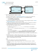
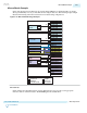
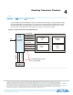
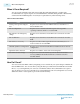
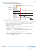
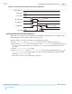

Figure 4-4: Transmitter Reset Sequence During Device Operation
Device Power Up
pll_cal_busy
tx_cal_busy
pll_powerdown
tx_analogreset
pll_locked
tx_digitalreset
1
2
3
1
1
t
tx_digitalreset
min 20 ns
t
pll_lock
max 10 µs
t
pll_powerdown
min 1 µs
Resetting the Receiver After Device Power-Up
Follow this reset sequence to ensure a reliable receiver initialization after initial power-up. Make sure the
RX CDR reference clock is valid and stable at device power-up.
The step numbers correspond to the numbers in the following waveform.
1. Hold rx_analogreset and rx_digitalreset active at power-up to hold the receiver in reset.
2. Make sure the rx_cal_busy status is deasserted. Deassert rx_analogreset for a minimum duration of
t
rx_analogreset
after the device enters user-mode. The CONF_DONE pin is asserted when the device enters
user-mode.
3. Wait for rx_is_lockedtodata to go high.
4. Deassert rx_digitalreset after rx_is_lockedtodata is asserted for a minimum duration of t
LTD
. If
rx_is_lockedtodata is asserted and toggles, you must wait another additional t
LTD
duration before
deasserting rx_digitalreset again.
The receiver is now out of reset and ready for operation.
UG-01143
2015.05.11
Resetting the Receiver After Device Power-Up
4-5
Resetting Transceiver Channels
Altera Corporation
Send Feedback