
User guide

Recommended Reset Sequence
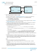
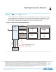
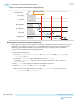
Figure 4-2: Transmitter and Receiver Reset Sequence
FPGA Device
Power Up/Operation
Ensure Calibration
Completed
PLL,TX/RX Analog
Reset Deasserted
Associated PLL/CDR
Locked
Release TX/RX
Digital Reset
TX/RX Reset
Completed
Transmit
or
Receive
1
2
3
5
6
7
4
Resetting the Transmitter After Device Power-Up
The FPGA automatically calibrates the PLL at every power-up before entering user-mode. Perform a reset
sequence after the device enters user-mode. Your User-Coded Reset Controller must comply with the
reset sequence below to ensure a reliable transmitter initialization after the initial power-up calibration.
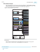
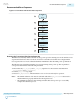
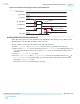
The following steps detail the transmitter reset sequence during device power-up. The step numbers
correspond to the numbers in the following waveform.
1. Ensure that the pll_cal_busy and tx_cal_busy signals are low. Deassert the transmitter PLL
pll_powerdown and tx_analogreset.
2. Wait for pll_locked to go high.
3. Deassert tx_digitalreset. The transmitter is now out of reset and ready for operation.
Note:
• The TX PLL reference clock must be valid and stable before pll_powerdown is deasserted so
that the TX PLL is properly calibrated for the target data run.
• The CLKUSR clock must be free running and stable after device power-up to successfully
complete the calibration process.
UG-01143
2015.05.11
Recommended Reset Sequence
4-3
Resetting Transceiver Channels
Altera Corporation
Send Feedback