
User guide
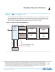

Native PHY IP Instances
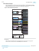
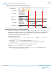
In this example, four Transceiver Native PHY IP instances and four 10GBASE-KR PHY IP instances are
used. Use the following data rates and configuration settings for the PHY IPs:
• 12.5 Gbps Interlaken with a bonded group of 10 channels
• Set the Interlaken 10x12.5 Gbps preset from the Arria 10 Transceiver Native PHY IP GUI.
• Refer to Interlaken on page 2-76 for more details.
• Custom multi-data rate 1.25G/9.8G/10.3125 Gbps non-bonded group of four channels
• Set the Number of data channels to 4.
• Set TX channel bonding to Not Bonded.
• Under the TX PMA tab, set the Number of TX PLL clock inputs per channel to 3.
• Under the RX PMA tab, set the Number of CDR reference clocks to 3.
• 1.25 Gbps Gigabit Ethernet with a non-bonded group of two channels
• Set the GIGE-1.25Gbps preset from the Arria 10 Transceiver Native PHY IP GUI.
• Change the Number of data channels to 2.
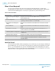
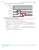
• PCIe Gen3 with a bonded group of 8 channels
• Set the PCIe PIPE Gen3x8 preset from the Arria 10 Transceiver Native PHY IP GUI.
• Under TX Bonding options , set the PCS TX channel bonding master to channel 5.
Note:
The PCS TX channel bonding master must be physically placed in channel 1 or channel 4
within a transceiver bank. In this example, the 5th channel of the bonded group is physically
placed at channel 1 in the transceiver bank.
• Refer to PCI Express (PIPE) on page 2-228 for more details.
• 10.3125 Gbps 10GBASE-KR non-bonded group of 4 channels
• Instantiate the Arria 10 1G/10GbE and 10GBASE-KR PHY IP four times, with one instance for
each channel.
• Refer to 10GBASE-KR PHY IP Core on page 2-125 for more details.
UG-01143
2015.05.11
Mix and Match Example
3-61
PLLs and Clock Networks
Altera Corporation
Send Feedback