
User guide

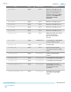
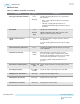
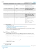

Port Range Clock Domain Description
pll_refclk0 input N/A Reference clock input port 0.
There are five reference clock
input ports. The number of
reference clock ports available
depends on the Number of
PLL reference clocks
parameter.
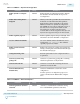
pll_refclk1 input N/A Reference clock input port 1.
pll_refclk2 input N/A Reference clock input port 2.
pll_refclk3 input N/A Reference clock input port 3.
pll_refclk4 input N/A Reference clock input port 4.
tx_serial_clk output N/A High speed serial clock output
port for GX channels.
Represents the x1 clock
network.
pll_locked output Asynchronous Active high status signal which
indicates if PLL is locked.
pll_pcie_clk output N/A Used for PCIe.
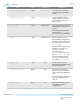
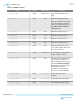
reconfig_clk0 input N/A Optional Avalon interface
clock. Used for PLL reconfigu‐
ration.
reconfig_reset0 input reconfig_clk0 Used to reset the Avalon
interface.
reconfig_write0 input reconfig_clk0 Active high write enable signal.
reconfig_read0 input reconfig_clk0 Active high read enable signal.
reconfig_address0[9:0] input reconfig_clk0 10-bit address bus used to
specify address to be accessed
for both read and write
operations.
reconfig_writedata0[31:0] input reconfig_clk0 32-bit data bus. Carries the
write data to the specified
address.
UG-01143
2015.05.11
fPLL IP Core
3-19
PLLs and Clock Networks
Altera Corporation
Send Feedback