
User guide
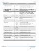

Reference Clock Multiplexer
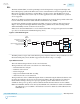
The refclk mux selects the reference clock to the PLL from the various available reference clock sources.
N Counter
The N counter divides the reference clock (refclk) mux's output. The N counter division helps lower the
loop bandwidth or reduce the frequency within the phase frequency detector's (PFD) operating range.
The N counter supports division factors from 1 to 32.
Phase Frequency Detector
The reference clock (refclk) signal at the output of the N counter block and the feedback clock (fbclk)
signal at the output of the M counter block are supplied as an inputs to the PFD. The output of the PFD is
proportional to the phase difference between the refclk and fbclk inputs. The PFD aligns the fbclk to
the refclk. The PFD generates an "Up" signal when the reference clock's falling edge occurs before the
feedback clock's falling edge. Conversely, the PFD generates a "Down" signal when the feedback clock's
falling edge occurs before the reference clock's falling edge.
Charge Pump and Loop Filter (CP + LF)
The PFD output is used by the charge pump and loop filter to generate a control voltage for the VCO. The
charge pump translates the "Up"/"Down" pulses from the PFD into current pulses. The current pulses are
filtered through a low pass filter into a control voltage that drives the VCO frequency.
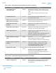
Voltage Controlled Oscillator
The fPLL has a ring oscillator based VCO. The VCO transforms the input control voltage into an
adjustable frequency clock.
VCO freq = 2 * M * Input reference clock/N. (N and M are the N counter and M counter division factors.)
L Counter
The L counter divides the VCO's clock output. When the fPLL acts as a transmit PLL, the output of the L
counter drives the clock generation block (CGB) and the TX PMA. The division factors supported are 1,
2, 4, and 8.
M Counter
The M counter divides the VCO's clock output. The M counter can select any VCO phase. The outputs of
the M counter and N counter have same frequency. M counter range is 8 to 127 in integer mode and 11 to
123 in fractional mode.
Delta Sigma Modulator
The delta sigma modulator is used in fractional mode. Depending on the value of K input, it modulates
the output of the M counter over time. The value of K input can be changed dynamically to use the fPLL
as replacement for the VCO.
The delta sigma modulator can be configured in 1st-order, 2nd-order, or 3rd-order mode.
C Counter
The C counter's design is identical to the M counter's design. However, the C counter is present in the
fPLL's output path and is not in the PLL's feedback path. The fPLL C counter division factors range from
1 to 512.
3-14
fPLL
UG-01143
2015.05.11
Altera Corporation
PLLs and Clock Networks
Send Feedback