
User guide
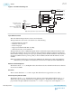

signal at the output of the N counter to the feedback clock (fbclk) signal. The PFD generates an "Up"
signal when the reference clock's falling edge occurs before the feedback clock's falling edge. Conversely,
the PFD generates a "Down" signal when the feedback clock's falling edge occurs before the reference
clock's falling edge.
Charge Pump and Loop Filter
The PFD output is used by the charge pump and loop filter (CP and LF) to generate a control voltage for
the VCO. The charge pump translates the "Up" or "Down" pulses from the PFD into current pulses. The
current pulses are filtered through a low pass filter into a control voltage that drives the VCO frequency.
The charge pump, loop filter, and VCO settings determine the bandwidth of the ATX PLL.
Lock Detector
The lock detector block indicates when the reference clock and the feedback clock are phase aligned. The
lock detector generates an active high pll_locked signal to indicate that the PLL is locked to its input
reference clock.
Voltage Controlled Oscillator
The voltage controlled oscillator (VCO) used in the ATX PLL is LC tank based. The output of charge
pump and loop filter serves as an input to the VCO. The output frequency of the VCO depends on the
input control voltage. The output frequency is adjusted based on the output voltage of the charge pump
and loop filter. Each ATX PLL has three LC tank circuits. Each tank circuit has multiple frequency banks
that support a continuous frequency range of operation from 7 GHz up to 14.15 GHz.
L Counter
The L counter divides the differential clocks generated by the ATX PLL. The division factors supported
are 1, 2, 4, 8, and 16. The L counter is not in the feedback path of the PLL.
M Counter
The M counter's output is the same frequency as the N counter's output. The VCO frequency is governed
by the equation:
VCO freq = 2 * M * input reference clock/N
An additional divider divides the high speed serial clock output of the VCO by 2 before it reaches the M
counter.
The M counter supports division factors in a continuous range from 8 to 127 in integer frequency
synthesis mode and 11 to 127 in fractional mode.
Delta Sigma Modulator
The delta sigma modulator is used only in fractional mode. It modulates the M counter divide value over
time so that the PLL can perform fractional frequency synthesis.
Related Information
Calibration on page 7-1
Instantiating the ATX PLL IP Core
The Arria 10 transceiver ATX PLL IP core provides access to the ATX PLLs in the hardware. One instance
of the PLL IP core represents one ATX PLL in the hardware.
UG-01143
2015.05.11
Instantiating the ATX PLL IP Core
3-5
PLLs and Clock Networks
Altera Corporation
Send Feedback