
User guide


5. Instantiate and configure your PLL.
6. Create a transceiver reset controller. You can use your own controller or use the Altera Transceiver
PHY Reset Controller IP.
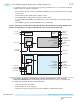
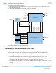
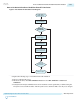
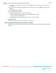
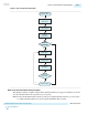
7. Connect the Native PHY IP to the PLL IP and the reset controller.
Figure 2-142: Connection Guidelines for a PCS Direct PHY Design
PLL IP
Data
Generator
Data
Verifier
Arria 10 Transceiver Native PHY
Reset Controller
pll_powerdown
rx_cdr_refclk
tx_serialclk0
pll_locked
pll_sel
reset
clk
pll_refclk
tx_ready
rx_ready
tx_parallel_data
tx_clkout
rx_parallel_data
rx_clkout
tx_serial_data
rx_serial_data
rx_is_lockedtodata
rx_cal_busy
tx_cal_busy
tx_analogreset
tx_digitalreset
rx_analogreset
rx_digitalreset
pll_cal_busy
8. Simulate your design to verify its functionality.
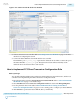
Simulating the Transceiver Native PHY IP Core
Use simulation to verify the Native PHY transceiver functionality. The Quartus II software supports
register transfer level (RTL) and gate-level simulation in both ModelSim
®
-Altera
®
and third-party
simulators. You run simulations using your Quartus II project files.
The following simulation flows are available:
• NativeLink with ModelSim-Altera—This flow simplifies simulation by allowing you to start a
simulation from the Quartus II software. This flow automatically creates a simulation script and
compiles design files, IP simulation model files, and Altera simulation library models.
• Custom Flow—This flow allows you to customize simulation for more complex requirements. You can
use this flow to compile design files, IP simulation model files, and Altera simulation library models
manually.
2-322
Simulating the Transceiver Native PHY IP Core
UG-01143
2015.05.11
Altera Corporation
Implementing Protocols in Arria 10 Transceivers
Send Feedback