
User guide
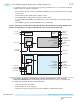
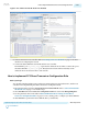
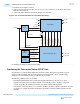
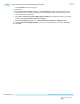
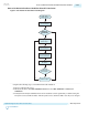
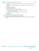
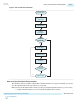

Figure 2-141: ATX PLL IP with GT Clock Lines Enabled
6. Create a transceiver reset controller. Refer to Resetting Transceiver Channels on page 4-1 for more
details about configuring the reset IP.
7. Connect the Native PHY IP to the PLL IP and the reset controller.
The ATX PLL's port tx_serial_clk_gt represents the dedicated GT clock lines. Connect this port to
the Native PHY IP's tx_serial_clk0 port. The Quartus II software will automatically use the
dedicated GT clocks instead of the x1 clock network.
How to Implement PCS Direct Transceiver Configuration Rule
Before you begin
You should be familiar with PCS Direct architecture, PMA architecture, PLL architecture, and the reset
controller before implementing PCS Direct Transceiver Configuration Rule.
1. Open the IP Catalog and select Arria 10 Transceiver Native PHY IP. Refer to Select and Instantiate
the PHY IP Core on page 2-2 for detailed steps.
2. Select PCS Direct from the Transceiver configuration rules list located under Datapath Options.
3. Use the parameter values in the tables in Native PHY IP Parameter Settings for PCS Direct
Transceiver Configuration Rules on page 2-316 as a starting point to configure your Native PHY IP.
4. Click Generate to generate the Native PHY IP (this is your RTL file).
UG-01143
2015.05.11
How to Implement PCS Direct Transceiver Configuration Rule
2-321
Implementing Protocols in Arria 10 Transceivers
Altera Corporation
Send Feedback