
User guide

Notes on grouping channels Ch0, Ch1, and Ch2:
• If channels 0 and 1 are configured as GT channels, channel 2 is unusable.
• If either channel 0 or 1 is configured as a GT channel, only one other channel can be used in this
grouping.
• If channels 0 and 1 are not configured as GT channels, this grouping can be all configured as GX
channels.
• If either channel 0 or 1 is used as a GT channel, then the ATX PLL adjacent to channel 0 and 1 must be
reserved for GT channel configurations.
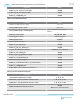
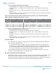
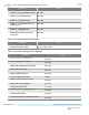
Table 2-187: Valid Permutations for GT and GX Channel Configuration in Transceiver Banks GXBL1E,
GXBL1F, GXBL1G, and GXBL1H for Channels 3, 4, and 5
GT
Transceive
r Channel
Configuration
A
Configuration
B
Configuration
C
Configuration
D
Configuration
E
Configuration F
Ch5 Unusable Unusable Unusable GX GX GX
Ch4 GT GT GX Unusable GT GX
Ch3 GT GX GT GT Unusable GX
Notes on grouping channels Ch3, Ch4, and Ch5:
• If channels 3 and 4 are configured as GT channels, channel 5 is unusable.
• If either channel 3 or 4 is configured as a GT channel, only one other channel can be used in this
grouping.
• If channels 3 and 4 are not configured as GT channels, this grouping can be all configured as GX
channels.
• If either channel 3 or 4 is used as a GT channel, then the ATX PLL adjacent to channel 3 and 4 must be
reserved for GT channel configurations.
Transceiver PHY IP
Arria 10 GT transceiver channels are implemented using the Native PHY IP with the Basic (Enhanced
PCS) transceiver configuration rule.
• To support data rates from 17.4 Gbps to 28.3 Gbps, the Enhanced PCS must be configured in low
latency mode. To configure the Enhanced PCS in low latency mode, do not enable any functional
blocks in the Enhanced PCS (that is, disable Block Synchronizer, Gearbox, Scrambler, and Encoder).
• You can also use the PCS-Direct mode, for data rates from 17.4 Gbps to 28.3 Gbps.
You can bundle several GT transceiver channels with one Native PHY IP instantiation, but you must
instantiate a separate ATX PLL IP for every ATX PLL used.
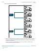
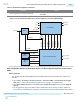
PLL and GT Transceiver Channel Clock Lines
The ATX PLL is used to provide the clock source for the GT transceiver channels. Each ATX PLL has two
dedicated GT clock lines which connect the PLL directly to the GT transceiver channels within a
transceiver bank. The top ATX PLL drives channels 3 and 4, and the bottom ATX PLL drives channels 0
and 1. These connections bypass the rest of the clock network for higher performance.
2-314
Transceiver PHY IP
UG-01143
2015.05.11
Altera Corporation
Implementing Protocols in Arria 10 Transceivers
Send Feedback