
User guide


6. Ensure that RX rate match FIFO mode is disabled.
7. Set the RX word aligner mode to bitslip.
8. Set the RX word aligner pattern length to 7 or 16.
Note: TX bitslip, RX bitslip, bit reversal, and polarity inversion modes are supported.
TX Bit Slip
To use the TX bit slip, select the Enable TX bitslip and Enable tx_std_bitslipboundarysel port options.
This adds the tx_std_bitslipboundarysel input port. The TX PCS automatically slips the number of
bits specified by tx_std_bitslipboundarysel. There is no port for TX bit slip. If there is more than one
channel in the design, tx_std_bitslipboundarysel ports are multiplied by the number of channels. You
can verify this feature by monitoring the tx_parallel_data port.
Enabling the TX bit slip feature is optional.
Note: The rx_parallel_data values in the following figures are based on the TX and RX bit reversal
features being disabled.
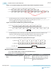
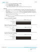
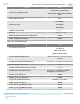
Figure 2-130: TX Bit Slip in 8-bit Mode
tx_parallel_data = 8'hbc. tx_std_bitslipboundarysel = 5'b00001 (bit slip by 1 bit).
tx_std_bitslipboundarysel
tx_parallel_data
rx_parallel_data
00001
bc
79
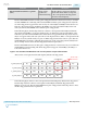
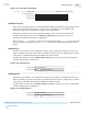
Figure 2-131: TX Bit Slip in 10-bit Mode
tx_parallel_data = 10'h3bc. tx_std_bitslipboundarysel = 5'b00011 (bit slip by 3 bits).
tx_std_bitslipboundarysel
tx_parallel_data
rx_parallel_data
00011
3bc
1e7
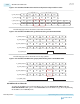
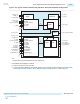
Figure 2-132: TX Bit Slip in 16-bit Mode
tx_parallel_data = 16'hfcbc. tx_std_bitslipboundarysel =5'b00011 (bit slip by 3 bits).
tx_std_bitslipboundarysel
tx_parallel_data
rx_parallel_data
00011
fcbc
5e7f
2-304
TX Bit Slip
UG-01143
2015.05.11
Altera Corporation
Implementing Protocols in Arria 10 Transceivers
Send Feedback