
User guide


The following ports are added:
• tx_datak
• rx_datak
• rx_runningdisp
• rx_disperr
• rx_errdetect
rx_datak and tx_datak indicate whether the parallel data is a control word or a data word. The incoming
8-bit data (tx_parallel_data) and the control identifier (tx_datak) are converted into a 10-bit data.
After a power on reset, the 8B/10B encoder takes the 10-bit data from the RD- column. Next, the encoder
chooses the 10-bit data from the RD+ column to maintain neutral disparity. The running disparity is
shown by rx_runningdisp.
8B/10B TX Disparity Control
The Disparity Control feature controls the running disparity of the output from the 8B/10B Decoder.
To enable TX Disparity Control, select the Enable TX 8B/10B Disparity Control option. The following
ports are added:
• tx_forcedisp—a control signal that indicates whether a disparity value has to be forced or not
• tx_dispval—a signal that indicates the value of the running disparity that is being forced
When the number of data channels is more than 1, tx_forcedisp and tx_dispval are shown as buses in
which each bit corresponds to one channel.
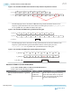
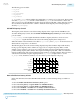
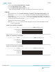
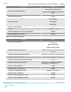
The following figure shows the current running disparity being altered in Basic single-width mode by
forcing a positive disparity /K28.5/ when it was supposed to be a negative disparity /K28.5/. In this
example, a series of /K28.5/ code groups are continuously being sent. The stream alternates between a
positive running disparity (RD+) /K28.5/ and a negative running disparity (RD-) /K28.5/ to maintain a
neutral overall disparity. The current running disparity at time n + 3 indicates that the /K28.5/ in time n +
4 should be encoded with a negative disparity. Because tx_forcedisp is high at time n + 4, and
tx_dispval is low, the /K28.5/ at time n + 4 is encoded as a positive disparity code group.
Current Running Disparity
clock
tx_in[7:0]
tx_forcedisp
BC BC BC BC BC BC BC
tx_ctrlenable
BC
dataout[9:0]
17C 283
RD–
17C
RD–RD+
283
RD+
283
RD+
283
RD+
17C
RD–
17C
RD–
n n + 1 n + 2 n + 3 n + 4 n + 5 n + 6 n + 7
tx_dispval
How to Enable Low Latency in Basic
In the Arria 10 Transceiver Native PHY IP Parameter Editor, use the following settings to enable low
latency:
1. Select the Enable 'Standard PCS' low latency mode option.
2. Select either low_latency or register FIFO in the TX FIFO mode list.
3. Select either low_latency or register FIFO in the RX FIFO mode list.
4. Select either Disabled or Serialize x2 in the TX byte serializer mode list.
5. Select either Disabled or Serialize x2 in the RX byte deserializer mode list.
UG-01143
2015.05.11
8B/10B TX Disparity Control
2-303
Implementing Protocols in Arria 10 Transceivers
Altera Corporation
Send Feedback