
User guide
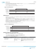

a bus in which each bit corresponds to a channel. As long as rx_std_bitrev_ena is asserted, the RX data
received by the core shows bit reversal.
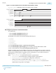
You can verify this feature by monitoring rx_parallel_data.
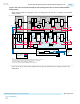
Figure 2-120: RX Bit Reversal
tx_parallel_data
rx_parallel_data
11111100001110111100
01
11
rx_std_bitrev_ena
rx_patterndetect
rx_syncstatus
00 01
11111100001110111100
1111110000111011110000111101110000111111
RX Byte Reversal
The RX byte reversal feature can be enabled in low latency, basic, and basic rate match mode. The word
aligner is available in any mode.
To enable this feature, select the Enable RX byte reversal and Enable rx_std_byterev_ena port options.
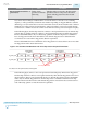
This adds rx_std_byterev_ena. If there is more than one channel in the design, rx_std_byterev_ena
becomes a bus in which each bit corresponds to a channel. As long as rx_std_byterev_ena is asserted,
the RX data received by the core shows byte reversal.
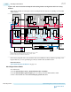
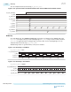
You can verify this feature by monitoring rx_parallel_data.
Figure 2-121: RX Byte Reversal
tx_parallel_data
rx_parallel_data
11111100001110111100
01
11
rx_std_byterev_ena
rx_patterndetect
rx_syncstatus
01
111111... 11111100001110111100
10
11101111001111110000
Rate Match FIFO in Basic (Single Width) Mode
Only the rate match FIFO operation is covered in these steps.
1. Select basic (single width) in the RX rate match FIFO mode list.
2. Enter values for the following parameters.
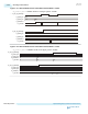
Parameter Value Description
RX rate match insert/delete +ve
pattern (hex)
20 bits of data
specified as a hexadec‐
imal string
The first 10 bits correspond to the skip pattern
and the last 10 bits correspond to the control
pattern. The skip pattern must have neutral
disparity.
2-298
RX Byte Reversal
UG-01143
2015.05.11
Altera Corporation
Implementing Protocols in Arria 10 Transceivers
Send Feedback