
User guide


Phase 0
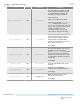
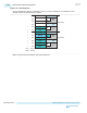
Phase 0 includes the following steps:
1. The upstream component enters Phase 0 of equalization during Recovery.Rcvrconfig by sending EQ
TS2 training sets with starting presets for the downstream component. EQ TS2 training sets may be
sent at 2.5 GT/s or 5 GT/s.
2. The downstream component enters Phase 0 of equalization after exiting Recovery.Speed at 8 GT/s. It
receives the starting presets from the training sequences and applies them to its transmitter. At this
time, the upstream component has entered Phase 1 and is operating at 8 GT/s.
3. To move to Phase 1, the receiver must have a BER < 10
-4
. The receiver should be able to decode
enough consecutive training sequences.
4. In order to move to Equalization Phase 1, the downstream component must detect training sets with
Equalization Control (EC) bits set to 2’b01.
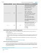
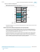
Phase 1
During Phase 1 of the equalization process, the link partners exchange Full Swing (FS) and Low
Frequency (LF) information. These values represent the upper and lower bounds for the TX coefficients.
The receiver uses this information to calculate and request the next set of transmitter coefficients.
1. The upstream component moves to EQ Phase 2 when training sets with EC bits set to 1’b0 are
captured on all lanes. It also sends EC=2’b10, starting pre-cursor, main cursor, and post-cursor
coefficients.
2. The downstream component moves to EQ Phase 2 after detecting these new training sets.
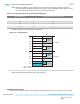
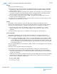
Phase 2 (Optional)
During Phase 2, the Endpoint tunes the TX coefficients of the Root Port. The TS1 Use Preset bit
determines whether the Endpoint uses presets for coarse resolution or coefficients for fine resolution.
Note:
You cannot perform Phase 2 tuning, when you are using the PHY IP Core for PCI Express (PIPE)
as an Endpoint. The PIPE interface does not provide any measurement metric to the Root Port to
guide coefficient preset decision making. The Root Port should reflect the existing coefficients and
move to the next phase. The default Full Swing (FS) value advertised by the Altera device is 40 and
Low Frequency (LF) is 13.
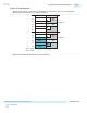
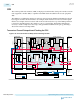
If you are using the PHY IP Core for PCI Express (PIPE) as the Root Port, the Endpoint can tune the Root
Port TX coefficients.
The tuning sequence typically includes the following steps:
1. The Endpoint receives the starting presets from the Phase 2 training sets sent by the Root Port.
2. The circuitry in the Endpoint receiver determines the BER. It calculates the next set of transmitter
coefficients using FS and LF. It also embeds this information in the Training Sets for the Link Partner
to apply to its transmitter.
The Root Port decodes these coefficients and presets, performs legality checks for the three transmitter
coefficient rules and applies the settings to its transmitter and also sends them in the Training Sets.
The three rules for transmitter coefficients are:
1. |C
-1
| <= Floor (FS/4)
2. |C
-1
|+C
0
+|C
+1
| = FS
3. C
0
-|C
-1
|-|C
+1
|>= LF
2-266
PHY IP Core for PCIe (PIPE) Link Equalization for Gen3 Data Rate
UG-01143
2015.05.11
Altera Corporation
Implementing Protocols in Arria 10 Transceivers
Send Feedback