
User guide
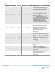
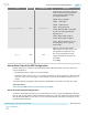
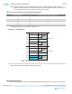
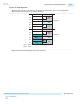
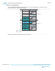
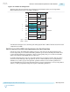

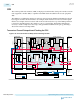
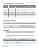

Figure 2-92: x4 Configuration
The figure below shows an alternate way of placing 4 bonded channels. In this case, the logical PCS
Master Channel number must be specified as channel 1.
CH5
CH4
CH3
CH2
CH1
CH0
CH5
CH4
CH3
CH2
CH1
CH0
Master CH
Data CH
fPLL
ATX
PLL
fPLL
ATX
PLL
fPLL
ATX
PLL
fPLL
ATX
PLL
Logical
Channel
Physical
Channel
0
1
Transceiver bank
Transceiver bank
2
3
Data CH
Data CH
Master
CGB
Master
CGB
Master
CGB
Master
CGB
Note: The physical channel 0 aligns with logical channel 0.
UG-01143
2015.05.11
Master Channel in Bonded Configurations
2-263
Implementing Protocols in Arria 10 Transceivers
Altera Corporation
Send Feedback