
User guide
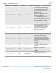

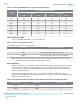

Port Direction Clock Domain Description
pipe_rx_status[2:0] Out rx_coreclkin
Signal encodes receive status and error
codes for the receive data stream and
receiver detection. The following
encodings are defined:
3'b000 - Receive data OK
3'b001 - 1 SKP added
3'b010 - 1 SKP removed
3'b011 - Receiver detected
3'b100 - Either 8B/10B or 128b/130b
decode error and (optionally) RX
disparity error
3'b101 - Elastic buffer overflow
3'b110 - Elastic buffer underflow
3'b111 - Receive disparity error, not
used if disparity error is reported
using 3'b100.
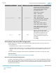
pipe_sw
Out N/A
Signal to clock generation buffer
indicating the rate switch request. Use
this signal for bonding mode only.
For non-bonded applications this
signal is internally connected to the
local CGB.
Active High
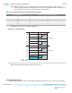
How to Place Channels for PIPE Configurations
Instead of the fitter or software model, the hardware dictates all the placement restrictions. The restric‐
tions are listed below:
• The channels must be contiguous for bonded designs.
• The master CGB is the only way to access x6 lines and must be used in bonded designs. The local CGB
cannot be used to route clock signals to slave channels because the local CGB does not have access to
x6 lines.
For channel placement guidelines when using Arria 10 Hard IP for PCIe, refer to the PCIe User Guide.
Related Information
Arria 10 Avalon-MM Interface for PCIe Solutions User Guide
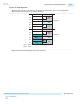
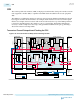
Master Channel in Bonded Configurations
For PCIe, both the PMA and PCS must be bonded. There is no need to specify the PMA Master Channel
because of the separate Master CGB in the hardware. However, you must specify the PCS Master Channel
through the Native PHY. You can choose any one of the data channels (part of the bonded group) as the
logical PCS Master Channel.
UG-01143
2015.05.11
How to Place Channels for PIPE Configurations
2-261
Implementing Protocols in Arria 10 Transceivers
Altera Corporation
Send Feedback