
User guide


configuration is based on the PIPE 2.0 specification. If you use a PIPE configuration, you must implement
the PHY-MAC layer using soft IP in the FPGA fabric.
Dynamic Switching Between Gen1 (2.5 Gbps) and Gen2 (5 Gbps)
In a PIPE configuration, Native PHY IP Core provides an input signal pipe_rate [1:0] that is function‐
ally equivalent to the RATE signal specified in the PCIe specification. A change in value from 2'b00 to
2'b01 on this input signal pipe_rate [1:0] initiates a data rate switch from Gen1 to Gen2. A change in
value from 2'b01 to 2'b00 on the input signal initiates a data rate switch from Gen2 to Gen1.
Transmitter Electrical Idle Generation
The PIPE interface block in Arria 10 devices puts the transmitter buffer in an electrical idle state when the
electrical idle input signal is asserted. During electrical idle, the transmitter buffer differential and
common mode output voltage levels are compliant with the PCIe Base Specification 2.0 for both PCIe
Gen1 and Gen2 data rates.
The PCIe specification requires the transmitter driver to be in electrical idle in certain power states.
Note: For more information about input signal levels required in different power states, refer to Power
State Management in the next section.
Power State Management
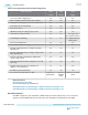
Table 2-155: Power States Defined in the PCIe Specification
To minimize power consumption, the physical layer device must support the following power states.
Power States Description
P0 Normal operating state during which packet data is transferred on the PCIe link.
P0s, P1, and P2 The PHY-MAC layer directs the physical layer to transition into these low-power
states.
The PIPE interface in Arria 10 transceivers provides a pipe_powerdown input port for each transceiver
channel configured in a PIPE configuration.
The PCIe specification requires the physical layer device to implement power-saving measures when the
P0 power state transitions to the low power states. Arria 10 transceivers do not implement these power-
saving measures except for putting the transmitter buffer in electrical idle mode in the lower power states.
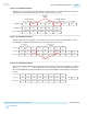
8B/10B Encoder Usage for Compliance Pattern Transmission Support
The PCIe transmitter transmits a compliance pattern when the Link Training and Status State Machine
(LTSSM) enters the Polling.Compliance substate. The Polling.Compliance substate assesses if the
transmitter is electrically compliant with the PCIe voltage and timing specifications.
Receiver Status
The PCIe specification requires the PHY to encode the receiver status on a 3-bit status signal
pipe_rx_status[2:0]. This status signal is used by the PHY-MAC layer for its operation. The PIPE
interface block receives status signals from the transceiver channel PCS and PMA blocks, and encodes the
status on the pipe_rx_status[2:0] signal to the FPGA fabric. The encoding of the status signals on the
pipe_rx_status[2:0] signal conforms to the PCIe specification.
UG-01143
2015.05.11
Dynamic Switching Between Gen1 (2.5 Gbps) and Gen2 (5 Gbps)
2-231
Implementing Protocols in Arria 10 Transceivers
Altera Corporation
Send Feedback