
User guide

You can use your own reset controller or use the Native PHY Reset Controller IP core.
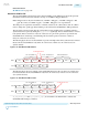
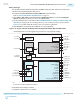
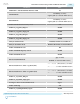
7. Connect the Native PHY IP to the PLL IP and the reset controller. Use the information in the figure
below to connect the ports.
Figure 2-37: Connection Guidelines for a GbE/GbE with IEEE 1588v2 PHY Design
reset
Pattern
Generator
Pattern
Checker
PLL
Reset
Controller
Arria 10
Transceiver
Native
PHY
tx_parallel_data
tx_datak
tx_clkout
pll_ref_clk
reset
tx_serial_clk
pll_locked
pll_powerdown
rx_ready
tx_ready
clk
reset
tx_digital_reset
tx_analog_reset
rx_digital_reset
rx_analog_reset
rx_is_lockedtodata
rx_parallel_data
rx_datak
rx_clkout
tx_serial_data
rx_serial_data
tx_cal_busy
rx_cal_busy
Note:
1. The pll_cal_busy signal is not available when using the CMU PLL.
pll_cal_busy (1)
rx_cdr_refclk
8. Simulate your design to verify its functionality.
Related Information
• Arria 10 Standard PCS Architecture on page 5-37
For more information about Standard PCS architecture
• Arria 10 PMA Architecture on page 5-1
For more information about PMA architecture
• Using PLLs and Clock Networks on page 3-49
For more information about implementing PLLs and clocks
• PLLs on page 3-3
PLL architecture and implementation details
• Resetting Transceiver Channels on page 4-1
Reset controller general information and implementation details
• Standard PCS Ports on page 2-68
Port definitions for the Transceiver Native PHY Standard Datapath
Native PHY IP Parameter Settings for GbE and GbE with IEEE 1588v2
2-106
Native PHY IP Parameter Settings for GbE and GbE with IEEE 1588v2
UG-01143
2015.05.11
Altera Corporation
Implementing Protocols in Arria 10 Transceivers
Send Feedback