
User guide


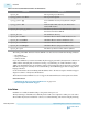


Table 2-66: Bit Reversal and Polarity Inversion
Name Direction Clock
Domain
Description
rx_std_byterev_ena[<n>-1:0]
Input Asynchro‐
nous
This control signal is available when the
PMA width is 16 or 20 bits. When asserted,
enables byte reversal on the RX interface.
Used if the MSB and LSB of the transmitted
data are erroneously swapped.
rx_std_bitrev_ena[<n>-1:0]
Input Asynchro‐
nous
When asserted, enables bit reversal on the
RX interface. Bit order may be reversed if
external transmission circuitry transmits the
most significant bit first. When enabled, the
receive circuitry receives all words in the
reverse order. The bit reversal circuitry
operates on the output of the word aligner.
tx_polinv[<n>-1:0]
Input Asynchro‐
nous
When asserted, the TX polarity bit is
inverted. Only active when TX bit polarity
inversion is enabled.
rx_polinv[<n>-1:0]
Input Asynchro‐
nous
When asserted, the RX polarity bit is
inverted. Only active when RX bit polarity
inversion is enabled.
rx_std_signaldetect[<n>-
1:0]
Output Asynchro‐
nous
When enabled, the signal threshold detection
circuitry senses whether the signal level
present at the RX input buffer is above the
signal detect threshold voltage. You can
specify the signal detect threshold using a
Quartus II Settings File (.qsf) assignment.
This signal is required for the PCI Express,
SATA and SAS protocols.
Related Information
• ATX PLL IP Core on page 3-6
• CMU PLL IP Core on page 3-24
• fPLL IP Core on page 3-15
• Ports and Parameters on page 6-24
• Transceiver PHY Reset Controller Interfaces on page 4-13
This section describes the top-level signals for the Transceiver PHY Reset Controller IP core.
• Analog Parameter Settings on page 8-1
2-74
Standard PCS Ports
UG-01143
2015.05.11
Altera Corporation
Implementing Protocols in Arria 10 Transceivers
Send Feedback