
User guide


Chapter 6: PHY IP Core for PCI Express (PIPE) 6–11
Interfaces
March 2012 Altera Corporation Altera Transceiver PHY IP Core
User Guide
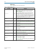
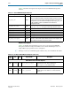
pipe_powerdown<n>[1:0]
(1)
Sink
This signal requests the PHY to change its power state to the specified
state. The following encodings are defined:
■ 2b’00– P0, normal operation
■ 2b’01–P0s, low recovery time latency, power saving state
■ 2b’10–P1, longer recovery time (64 us maximum latency), lower power
state
■ 2b’11–P2, lowest power state. (not supported)
pipe_rxpolarity
Sink
When 1, instructs the PHY layer to invert the polarity on the 8B/10B
receiver decoding block.
pipe_rxelecidle
Source When asserted, indicates receiver detection of an electrical idle.
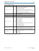
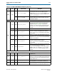
pipe_phystatus
Source This signal is used to communicate completion of several PHY requests.
pipe_rxstatus<n>[2:0]
(1)
Source
This signal encodes receive status and error codes for the receive data
stream and receiver detection.The following encodings are defined:
■ 000–receive data OK
■ 001–1 SKP added
■ 010–1 SKP removed
■ 011–Receiver detected
■ 100–Both 8B/10B decode error and (optionally) RX disparity error
■ 101–Elastic buffer overflow
■ 110–Elastic buffer underflow
■ 111–Receive disparity error.
rx_eidleinfersel[<n>-1:0]
Sink
When asserted high, the electrical idle state is inferred instead of being
identified using analog circuitry to detect a device at the other end of the
link. You can select electrical idle inferencing, by setting the Enable
electrical idle inferencing parameter in the parameter editor to true.
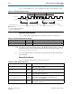
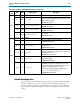
pipe_txswing
Source
Indicates whether the transceiver is using full- or low-swing voltages as
defined by the
tx_pipemargin
.
■ 0–Full swing
■ 1–Low swing
Note to Table 6–8:
(1) <n> is the number of lanes. The PHY (PIPE) supports ×1, ×4, ×8 operation.
Table 6–8. PIPE Interface (Part 2 of 2)
Signal Name Direction Description