
User guide

Chapter 6: PHY IP Core for PCI Express (PIPE) 6–3
Parameter Settings
March 2012 Altera Corporation Altera Transceiver PHY IP Core
User Guide
Analog Options
You specify the analog parameters for Stratix V devices using the Quartus II
Assignment Editor, the Pin Planner, or through the Quartus II Settings File (.qsf). The
default values for analog options fall into three categories:
■ Global— These parameters have default values that are independent of other
parameter settings.
■ Computed—These parameters have an initial default value that is recomputed
based on other parameter settings.
■ Proxy—These parameters have default values that are place holders. The
Quartus II software selects these initial default values based on your design;
however, Altera recommends that you replace these defaults with values that
match your electrical board specification.
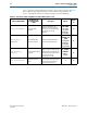
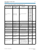
PLL type
CMU
ATX
You can select either the CMU or ATX PLL. The CMU PLL has a larger
frequency range than the ATX PLL. The ATX PLL is designed to
improve jitter performance and achieves lower channel-to-channel
skew; however, it supports a narrower range of data rates and
reference clock frequencies. For example, if a base data rate of
2500 Mbps is not available with the ATX PLL and a 100 MHz reference
clock; however, base data rates of 5000 Mbps or 10000 Mbps are
possible with the ATX PLL and 100 MHz reference clock. Another
advantage of the ATX PLL is that it does not use a transceiver channel,
while the CMU PLL does.
PLL reference clock
frequency
100 MHz
125 MHz
If you specify a CMU PLL for the TX PLL, you can use either the
100 MHz or 125 MHz input reference clock.
Deserialization factor 8, 16
Specifies the width of the interface between the PHYMAC and PHY
(PIPE). Using the 16-bit interface, reduces the required clock
frequency by half at the expense of extra FPGA resources.
PIPE low latency
synchronous mode
On/Off When enabled, the rate match FIFO is in low latency mode.
Run length 5–160 Specifies the legal number of consecutive 0s or 1s.
Enable electrical idle
inferencing
True/False
When True, enables the PIPE interface to infer electrical idle instead of
detecting electrical idle using analog circuitry. For more information
about inferring electrical idle, refer to “Section 4.2.3.4 Inferring
Electrical Idle” in the
PCI Express Base Specification 2.0.
Table 6–3. General Options (Part 2 of 2)
Name
Value
Description