
User guide

6–2 Chapter 6: PHY IP Core for PCI Express (PIPE)
Resource Utilization
Altera Transceiver PHY IP Core March 2012 Altera Corporation
User Guide
Resource Utilization
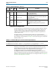
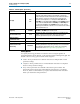
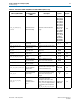
Table 6–2 shows the typical expected device resource utilization for different
configurations using the current version of the Quartus II software targeting a
Stratix V GX device.
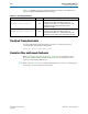
Parameter Settings
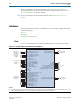
To configure the PHY IP core for PCI Express in the parameter editor, click Installed
Plug-Ins > Interfaces > PCI Express > PHY IP Core for PCI Express (PIPE) v11.1.
This PHY IP core is only available when you select the Stratix V device family.
General Options
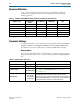
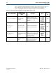
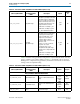
This section describes the PHY IP core for PCI Express parameters, which you can set
using the parameter editor. Table 6–3 lists the settings available on General Options
tab.
Table 6–2. PCI Express PHY (PIPE) Performance and Resource Utilization—Stratix V Devices
Number of Lanes
Combinational
ALUTs
Logic Registers Memory Bits PLLs
Gen1 ×1 460 285 0 2
Gen1 ×4 530 373 0 5
Gen1 ×8 590 425 0 9
Gen2 ×1 460 295 0 2
Gen2 ×4 530 373 0 5
Gen2 ×8 590 425 0 9
Table 6–3. General Options (Part 1 of 2)
Name
Value
Description
Device family Stratix V Supports only Stratix V devices
Number of lanes 1, 4, 8 The total number of duplex lanes
Protocol version
Gen1 (2.5 Gbps)
Gen2 (5.0 Gbps)
Specifies the protocol version. Gen1 implements
PCI Express Base
Specification 1.1.
Gen2 implements PCI Express Base
Specification 2.0.
Base data rate
1 × Lane rate
2 × Lane rate
4 × Lane rate
8 × Lane rate
The base data rate is the output clock frequency of the PLL. Select a
base data rate that minimizes the number of PLLs required to
generate all the clock s required for data transmission. By selecting an
appropriate base data rate, you can achieve the required data rate by
changing the divider used by the clock generation block.