
User guide

Chapter 5: Interlaken PHY IP Core 5–13
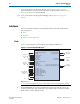
Interfaces
March 2012 Altera Corporation Altera Transceiver PHY IP Core
User Guide
Registers
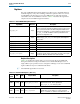
The Avalon-MM PHY management interface provides access to the Interlaken PCS
and PMA registers, resets, error handling, and serial loopback controls. You can use
an embedded controller acting as an Avalon-MM master to send read and write
commands to this Avalon-MM slave interface. Table 5–11 describes the signals that
comprise the Avalon-MM management interface.
Register Descriptions
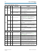
Table 5–12 specifies the registers that you can access using the Avalon-MM PHY
management interface using word addresses and a 32-bit embedded processor. A
single address space provides access to all registers. Writing to reserved or undefined
register addresses may have undefined side effects.
1 All undefined register bits are reserved.
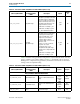
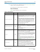
Table 5–11. Avalon-MM PCS Management Interface
Signal Name Direction Description
phy_mgmt_clk
Input
Avalon-MM clock input.
There is no frequency restriction for Stratix V devices; however, if you
plan to use the same clock for the PHY management interface and
transceiver reconfiguration, you must restrict the frequency range of
phy_mgmt_clk
to 100–125 MHz to meet the specification for the
transceiver reconfiguration clock.
phy_mgmt_clk_reset
Input
Global reset signal that resets the entire Interlaken PHY. Changed
definition of
phy_mgmt_clk_reset
. This signal is active high and
level sensitive. .
phy_mgmt_addr[8:0]
Input 9-bit Avalon-MM address.
phy_mgmt_writedata[31:0]
Input Input data.
phy_mgmt_readdata[31:0]
Output Output data.
phy_mgmt_write
Input Write signal.
phy_mgmt_read
Input Read signal.
phy_mgmt_waitrequest
Output
When asserted, indicates that the Avalon-MM slave interface is unable
to respond to a read or write request. When asserted, control signals
to the Avalon-MM slave interface must remain constant.
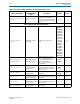
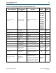
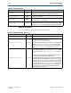
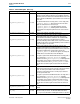
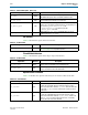
Table 5–12. Interlaken PHY Registers (Part 1 of 3)
Word
Addr
Bits R/W Register Name Description
PMA Common Control and Status Registers
0x022 [31:0] RO
pma_tx_pll_is_locked
Bit[P] indicates that the TX CMU PLL (P) is locked to the
input reference clock. There is typically one
pma_tx_pll_is_locked
bit per system.
Reset Control Registers–Automatic Reset Controller
0x041 [31:0] RW
reset_ch_bitmask
Reset controller channel bitmask for digital resets. The
default value is all 1s. Channel <
n
> can be reset when
bit<
n
> = 1. Channel <
n
> cannot be reset when bit<
n
> = 0.