
User guide

Chapter 3: 10GBASE-R PHY IP Core 3–19
Interfaces
March 2012 Altera Corporation Altera Transceiver PHY IP Core
User Guide
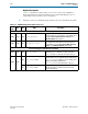
0x044
[31:0] RW
reset_fine_control
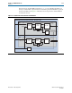
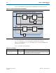
You can use the
reset_fine_control
register to create
your own reset sequence. The reset control module,
illustrated in Figure 1–1 on page 1–2, performs a standard
reset sequence at power on and whenever the
phy_
mgmt_clk_reset
is asserted. Bits [31:4,0] are
reserved.
[31:4,0] RW
Reserved
It is safe to write 0s to reserved bits.
[1] RW
reset_tx_digital
Writing a 1 causes the internal TX digital reset signal to be
asserted, resetting all channels enabled in
reset_ch_bitmask. You must write a 0 to clear the
reset condition.
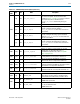
[2] RW
reset_rx_analog
Writing a 1 causes the internal RX digital reset signal to be
asserted, resetting the RX analog logic of all channels
enabled in reset_ch_bitmask. You must write a 0 to
clear the reset condition.
[3] RW
reset_rx_digital
Writing a 1 causes the RX digital reset signal to be
asserted, resetting the RX digital channels enabled in
reset_ch_bitmask. You must write a 0 to clear the
reset condition.
PMA Channel Control and Status
0x061 [31:0] RW
phy
_
serial
_
loopback
Writing a 1 to channel <n> puts channel <n> in serial
loopback mode. For information about pre- or
post-CDRserial loopback modes, refer to “Loopback
Modes” on page 10–39 .
0x064 [31:0] RW
pma_rx_set_locktodata
When set, programs the RX CDR PLL to lock to the
incoming data. Bit <n> corresponds to channel <n>.
0x065 [31:0] RW
pma_rx_set_locktoref
When set, programs the RX CDR PLL to lock to the
reference clock. Bit <n> corresponds to channel <n>.
0x066 [31:0] R
pma_rx_is_lockedtodata
When asserted, indicates that the RX CDR PLL is locked to
the RX data, and that the RX CDR has changed from LTR to
LTD mode. Bit <n> corresponds to channel <n>.
0x067 [31:0] R
pma_rx_is_lockedtoref
When asserted, indicates that the RX CDR PLL is locked to
the reference clock. Bit <n> corresponds to channel <n>.
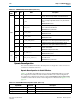
10GBASE-R PCS
0x080 [31:0] RW
INDIRECT_ADDR
Provides for indirect addressing of all PCS control and
status registers. Use this register to specify the logical
channel number of the PCS channel you want to access.
0x081
[2] RW
RCLR_ERRBLK_CNT
When set to 1, clears the error block count register.
To block: Block synchronizer
[3] RW
RCLR_BER_COUNT
When set to 1, clears the bit error rate (BER) register. This
bit is only for Stratix IV devices.
To block: BER monitor
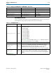
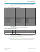
Table 3–17. 10GBASE-R Register Descriptions (Part 2 of 3)
Word
Addr
Bit R/W Name Description