
User guide

3–16 Chapter 3: 10GBASE-R PHY IP Core
Interfaces
Altera Transceiver PHY IP Core March 2012 Altera Corporation
User Guide
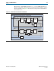
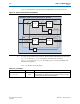
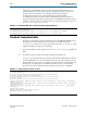
Figure 3–5 illustrates the clock generation and distribution for Stratix V devices.
1 To ensure proper functioning of the PCS, the maximum PPM difference between the
pll_ref_clk
and
xgmii_tx_clk
clock inputs is 100 PPM. You should use
xgmii_rx_clk
to drive
xgmii_tx_clk
. The CDR logic recovers 257.8125 MHz clock
from the incoming data.
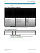
Table 3–15 describes the clock inputs.
Figure 3–5. Stratix V Clock Generation and Distribution
pll_ref_clk
644.53125 MHz
10.3125
Gbps serial
257.8125
MHz
257.8125
MHz
156.25 MHz
10GBASE-R Hard IP Transceiver Channel - Stratix V
TX
RX
TX PCS
40
64
TX PMA
10.3125
Gbps serial
RX PCS
4064
RX PMA
TX PLL
8/33
fPLL
xgmii_rx_clk
xgmii_tx_clk
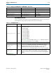
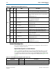
Table 3–14. Clock Signals
Signal Name Direction Description
pll_ref_clk
Input
For Stratix IV GT devices, the TX PLL reference clock which must be
644.53125 MHz. For Stratix V devices, the TX PLL reference clock can
be either 644.53125 MHz or 322.265625 MHz.