
User guide

3–14 Chapter 3: 10GBASE-R PHY IP Core
Interfaces
Altera Transceiver PHY IP Core March 2012 Altera Corporation
User Guide
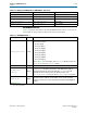
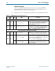
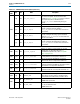
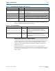
Table 3–12 provides the mapping from the XGMII RX interface to the XGMII SDR
interface.
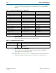
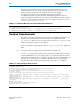
Status Interface
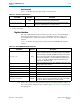
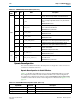
Table 3–13 describes signals that provide status information.
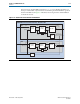
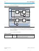
Clocks, Reset, and Powerdown
The
phy_mgmt_clk_reset
signal is the global reset that resets the entire PHY. A
positive edge on this signal triggers a reset.
f Refer to the Reset Control and Power Down chapter in volume 2 of the Stratix IV Device
Handbook for additional information about reset sequences in Stratix IV devices.
Table 3–12. Mapping from XGMII RX Bus to the XGMII SDR Bus
Signal Name XGMII Signal Name Description
xgmii_rx_dc[7:0] xgmii_sdr_data[7:0]
Lane 0 data
xgmii_rx_dc[8] xgmii_sdr_ctrl[0]
Lane 0 control
xgmii_rx_dc[16:9] xgmii_sdr_data[15:8]
Lane 1 data
xgmii_rx_dc[17] xgmii_sdr_ctrl[1]
Lane 1 control
xgmii_rx_dc[25:18] xgmii_sdr_data[23:16]
Lane 2 data
xgmii_rx_dc[26] xgmii_sdr_ctrl[2]
Lane 2 control
xgmii_rx_dc[34:27] xgmii_sdr_data[31:24]
Lane 3 data
xgmii_rx_dc[35] xgmii_sdr_ctrl[3]
Lane 3 control
xgmii_rx_dc[43:36] xgmii_sdr_data[39:32]
Lane 4 data
xgmii_rx_dc[44] xgmii_sdr_ctrl[4]
Lane 4 control
xgmii_rx_dc[52:45] xgmii_sdr_data[47:40]
Lane 5 data
xgmii_rx_dc[53] xgmii_sdr_ctrl[5]
Lane 5 control
xgmii_rx_dc[61:54] xgmii_sdr_data[55:48]
Lane 6 data
xgmii_rx_dc[62] xgmii_sdr_ctrl[6]
Lane 6 control
xgmii_rx_dc[70:63] xgmii_sdr_data[63:56]
Lane 7 data
xgmii_rx_dc[71] xgmii_sdr_ctrl[7]
Lane 7 control
Table 3–13. 10GBASE-R Receive Status Outputs
Signal Name Direction Description
block_lock
Output Asserted to indicate that the block synchronizer has established synchronization.
hi_ber
Output
Asserted by the BER monitor block to indicate a Sync Header high bit error rate
greater than 10
-4
.