
User guide

3–12 Chapter 3: 10GBASE-R PHY IP Core
Interfaces
Altera Transceiver PHY IP Core March 2012 Altera Corporation
User Guide
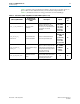
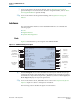
SDR XGMII TX Interface
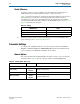
Table 3–9 describes the signals in the SDR XGMII TX interface. These signals are
driven from the MAC to the PCS. This is an Avalon-ST sink interface.
f For more information about the Avalon-ST protocol, including timing diagrams, refer
to the Avalon Interface Specifications.
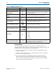
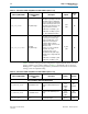
Table 3–10 provides the mapping from the XGMII TX interface to the XGMII SDR
interface.
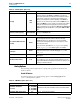
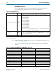
Table 3–9. SDR XGMII TX Inputs
(1)
Signal Name Direction Description
xgmii_tx_dc[<n>71:0]
Sink
Contains 8 lanes of data and control for XGMII. Each lane consists of 8 bits of
data and 1 bit of control.
■ Lane 0–[7:0]/[8]
■ Lane 1–[16:9]/[17]
■ Lane 2–[25:18]/[26]
■ Lane 3–[34:27]/[35]
■ lane 4–[43:36]/[44]
■ Lane 5–[52:45]/[53]
■ Lane 6–[61:54]/[62]
■ Lane 7–[70:63]/[71]
Refer to Table 3–10 for the mapping of the
xgmii_tx_dc
data and control to the
xgmii_sdr_data
and
xgmii_sdr_ctrl
signals.
tx_ready
Output
Asserted when the TX channel is ready to transmit data. Because the
readyLatency
on this Avalon-ST interface is 0, the MAC may drive
tx_ready
as
soon as it comes out of reset.
xgmii_tx_clk
Input The XGMII TX clock which runs at 156.25 MHz.
Note to Table 3–9:
(1) <n> is the channel number
Table 3–10. Mapping from XGMII TX Bus to XGMII SDR Bus (Part 1 of 2)
Signal Name XGMII Signal Name Description
xgmii_tx_dc[7:0] xgmii_sdr_data[7:0]
Lane 0 data
xgmii_tx_dc[8] xgmii_sdr_ctrl[0]
Lane 0 control
xgmii_tx_dc[16:9] xgmii_sdr_data[15:8]
Lane 1 data
xgmii_tx_dc[17] xgmii_sdr_ctrl[1]
Lane 1 control
xgmii_tx_dc[25:18] xgmii_sdr_data[23:16]
Lane 2 data
xgmii_tx_dc[26] xgmii_sdr_ctrl[2]
Lane 2 control
xgmii_tx_dc[34:27] xgmii_sdr_data[31:24]
Lane 3 data
xgmii_tx_dc[35] xgmii_sdr_ctrl[3]
Lane 3 control
xgmii_tx_dc[43:36] xgmii_sdr_data[39:32]
Lane 4 data
xgmii_tx_dc[44] xgmii_sdr_ctrl[4]
Lane 4 control
xgmii_tx_dc[52:45] xgmii_sdr_data[47:40]
Lane 5 data