
User guide

11–6 Chapter 11: Migrating from Stratix IV to Stratix V Devices
PHY IP Core for PCI Express PHY (PIPE)
Altera Transceiver PHY IP Core March 2012 Altera Corporation
User Guide
PHY IP Core for PCI Express PHY (PIPE)
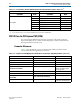
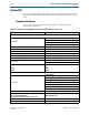
This section lists the differences between the parameters and signals for the PCI
Express PHY (PIPE) IP core and the ALTGX megafunction when configured in the
PCI Express (PIPE) functional mode.
Parameter Differences
Table 11–4 lists the PHY IP core for PCI Express PHY (PIPE) parameters and the
corresponding ALTGX megafunction parameters.
Not available
phy_mgmt_clk_rst
1
phy_mgmt_clk
1
phy_mgmt_address
[8:0]
phy_mgmt_read
1
phy_mgmt_readdata
[31:0]
phy_mgmt_write
1
phy_mgmt_writedata
[31:0]
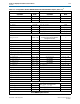
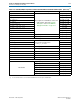
Note to Table 11–3:
(1) <n> = the number of lanes. <d> = the total deserialization factor from the pin to the FPGA fabric.
Table 11–3. Correspondences between XAUI PHY Stratix IV GX and Stratix V Device Signals (Part 3 of 3)
(1)
Stratix IV GX Devices Stratix V Devices
Signal Name Width Signal Name Width
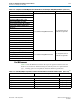
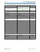
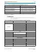
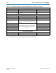
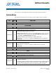
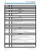
Table 11–4. Comparison of ALTGX Megafunction and PHY IP Core for PCI Express PHY (PIPE) Parameters (Part 1 of 2)
ALTGX Parameter Name (Default Value) PCI Express PHY (PIPE) Parameter Name Comments
Number of channels Number of Lanes —
Channel width Deserialization factor —
Subprotocol Protocol Version —
input clock frequency PLL reference clock frequency —
Starting Channel Number —
Automatically set to 0.
Quartus II software handles
lane assignments.
Enable low latency sync
pipe_low_latency_syncronous_mode
—
Enable RLV with run length of
pipe_run_length_violation_checking
Always on
Enable electrical idle inference
functionality
Enable electrical idle inferencing —
—
phy_mgmt_clk_in_mhz
For embedded reset
controller to calculate delays