
User guide


Chapter 10: Transceiver Reconfiguration Controller 10–35
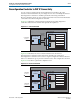
Understanding Logical Channel Numbering
March 2012 Altera Corporation Altera Transceiver PHY IP Core
User Guide
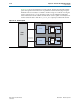
One PHY IP Core Instance with Eight Bonded Channels
This example requires the Quartus II Fitter to place channels in two, contiguous
transceiver banks. To preserve flexibility for the Fitter, each channel and TX PLL is
numbered separately. During place and route, the Fitter maps the eight logical TX
PLLs to a single physical TX PLL.
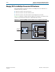
Table 10–26 illustrates the logical channel numbering. In this table, logical address 0
accesses data channel 0 and logical address 8 accesses the TX PLL for data channel 0;
logical address 1 accesses data channel 1 and logical address 9 accesses the TX PLL for
data channel 1, and so on. In simulation, to reconfigure the TX PLL for channel 0,
specify logical address 8 in the Streamer module’s
logical
channel
number
. The
Streamer module maps the logical channel to the physical channel which would be
the same value for all eight channels.
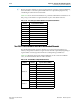
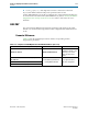
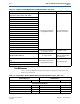
Table 10–25. Channel Ordering for Concatenated Transceiver Instances
Logical Interface Number PHY Instance, Interface, or PLL
0–3 Instance 0, interfaces 0–3.
4-7
Instance 0, TX PLL. The Fitter assigns all 4 logical TX PLLs
to a single physical PLL.
8-11 Instance 1, interfaces 0–3.
12-15
Instance 1, TX PLL. The Fitter assigns all 4 logical TX PLLs
to a single physical PLL.
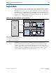
Table 10–26. Initial Number of Eight Bonded Channels
Channel Logical Channel Number
Channel 0 0
Channel 1 1
Channel 2 2
Channel 3 3
Channel 4 4
Channel 5 5
Channel 6 6
Channel 7 7
CMU 0 8
CMU 1 9
CMU 2 10
CMU 3 11
CMU 4 12
CMU 5 13
CMU 6 14
CMU 7 15