
User guide

10–30 Chapter 10: Transceiver Reconfiguration Controller
Procedures for Reconfiguration
Altera Transceiver PHY IP Core March 2012 Altera Corporation
User Guide
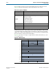
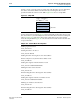
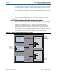
In Steps 3 and 4, you must specify an offset value and offset data. You can determine
the values of the offset address and offset data by examining the data records
specified in either the channel or PLL MIFs. Figure 10–6 shows a sample MIF.
For the sample data record in Figure 10–6, the length field specifies three data records.
The offset value is 0, as indicated by bits 10–0. The offset data are the three subsequent
entries. Example 10–5 performs a direct write in Streamer mode 1. This example
writes the sample MIF in Figure 10–6 into the Streamer module which writes this data
to logical channel 0.
Figure 10–6. Sample MIF
Example 10–5. Streamer Mode 1 Reconfiguration
#Setting logical channel 0
write_32 0x38 0x0
#Setting Streamer to mode to 1
write_32 0x3A 4'b0100
#Setting Streamer offset register to the offset address
#In the example record, the first offset address is 0x0
write_32 0x3B 0x0
#Setting data register with the first data record
write_32 0x3C 16'b0010100000100000
#Writing first data to the Streamer
write_32 0x3A 0x1
#Incrementing Streamer offset register offset address
write_32 0x3B 0x1
#Setting data register with the second data record
write_32 0x3C 16'b0010001110110000
#Writing second data to the Streamer
write_32 0x3A 0x1
#Incrementing Streamer offset register offset address
write_32 0x3B 0x2
0 0 0 1 1 0 0 0 0 0 0 0 0 0 0 0
0 0 1 0 1 0 0 0 0 0 1 0 0 0 0 0
0 0 1 0 0 0 1 1 1 0 1 1 0 0 0 0
1 0 0 0 0 0 0 1 1 1 0 1 0 1 0 0
Length = 3 Offset Value = 0
Offset Data
15
1110
0