
User guide

10–26 Chapter 10: Transceiver Reconfiguration Controller
Streamer Module
Altera Transceiver PHY IP Core March 2012 Altera Corporation
User Guide
For a non-data record, the opcode is represented by the lower 5-bits in the record.
Table 10–24 lists the supported opcodes and describes the data content.
For data records, the low-order 11 bits provide a logical offset address. In this case, the
length
field indicates the number of data records that are written into the specified
address. For example, if the length field is set to two, the next two records belong the
data record and are written into the offset address.
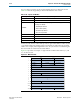
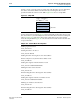
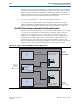
Figure 10–5 provides an example of a typical Stratix V MIF format. Entries 3, 7, and
<n> are data records.
Table 10–24. Opcodes for MIF Files
Opcode Opcode Description
5’b00000 Reserved
5’b00001 Start of MIF
5’b00010
Channel format indicator specifying the MIF channel type. The following
encodings are defined:
■ 2’b00: Duplex channel
■ 2’b01: TX PLL (CMU)
■ 2’b10: RX only channel
■ 2’b11: TX only channel
5’b00011 CDR Input Clock switch
5’b00100 PLL switch
5’b00101-5’b11110 Reserved
5’b11111 End of MIF (EOM)
Figure 10–5. MIF File Format
Length = 00
1
2
3
4
5
6
7
8
<n>
<n>
+1
<n>
+2
<n>
+3
MIF/Quartus Version Opcode = Start of MIF
Length = 0 Input Clock Index Opcode = Input Clock Index
Length = 0 PLL Index Opcode = PLL
Length = 0 Reserved Opcode = End of MIF
Length = 3 Offset Address N
Data for Offset N
Length = 1 Offset M
Data for Offset M
Data for Offset N + 1
Data for Offset N + 2
Length = 2 Offset Address L
Data for Offset L
Data for Offset L + 1
15 11 10
.
.
.
.
.
.
504