
User guide

Chapter 10: Transceiver Reconfiguration Controller 10–23
Streamer Module
March 2012 Altera Corporation Altera Transceiver PHY IP Core
User Guide
1 All undefined register bits are reserved.
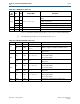
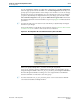
Table 10–22. Streamer Module Registers
PHY
Addr
Bits R/W Register Name Description
7’h38 [9:0] RW
logical channel number
The logical channel number. Must be specified when
performing dynamic updates. The Transceiver
Reconfiguration Controller maps the logical address to the
physical address.
7’h39 [9:0] R
physical channel address
The physical channel address. The Transceiver
Reconfiguration Controller maps the logical address to the
physical address.
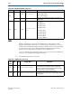
7’h3A
[9] R
control and status
Error
. When asserted, indicates an error. This bit is asserted
if any of the following conditions occur:
■ The channel address is invalid.
■ The PHY address is invalid.
■ The
offset
register address is invalid.
[8] R
Busy
. When asserted, indicates that a reconfiguration
operation is in progress.
[3:2] RW
Mode
. The following encodings are defined:
■ 2’b00: MIF. This mode continuously reads and transfers a
.mif file, which contains the reconfiguration data.
■ 2’b01: Direct Write. In this mode, you specify a logical
channel, a register offset, and data. Depending on the
logical channel specified, the Transceiver Reconfiguration
Controller may mask some of the data specified to prevent
read-only values that were optimized during startup, from
being over-written. In particular, this mode protects the
following settings:
■ Decision feedback equalization controls
■ RX buffer offset calibration adjustments
■ Duty cycle distortion adjustments
■ PMA clock settings
■ 2’b10: Reserved
■ 2’b11: Reserved
[1] W
Read
. Writing a 1 to this bit triggers a read operation. This bit
is self clearing.
[0] W
Write
. Writing a 1 to this bit triggers a write operation. This
bit is self clearing.
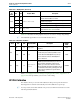
7’h3B [15:0] RW
offset
When the
MIF mode
= 2’b00, the
offset
register specifies a
an internal MIF Streamer register. Refer to Table 10–23 for
definitions of these registers. When
MIF Mode
= 2’b01,
offset
register specifies register in the transceiver
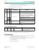
7’h3C [31:0] RW
data
When the
MIF Mode
= 2’b00, the
data
register stores read
or write data for indirect access to the location specified in
the
offset
register. When
MIF Mode
= 2’b01,
data
holds an
update for transceiver to be dynamically reconfigured.