
User guide

10–22 Chapter 10: Transceiver Reconfiguration Controller
Streamer Module
Altera Transceiver PHY IP Core March 2012 Altera Corporation
User Guide
■ Reference clock inputs
■ FPGA fabric transceiver width
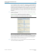
When you select Enable Channel Interface, in the Custom and Low Latency
Transceiver PHY GUIs, the default width of the FPGA fabric to transceiver interface
increases for both the Standard and 10G datapaths as follows:
■ Standard datapath—The TX interface is 44 bits. The RX interface is 64 bits.
■ 10G datapath— TX only, RX only, and duplex channels are all 64 bits.
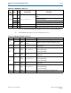
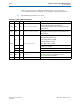
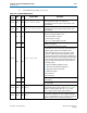
However, depending upon the FPGA fabric transceiver width specified, only a subset
of the 64 bits may carry valid data. Specifically, in the wider bus, only the lower <n>
bits are used, where <n> is equal to the width of the FPGA fabric width specified in
the transceiver PHY IP core. Table 10–21 illustrates this point for the 10G datapath,
showing three examples where the FPGA fabric interface width is less than 64 bits.
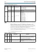
PLL Reconfiguration
If you turn on Enable PLL reconfiguration support block in the Transceiver
Reconfiguration Controller GUI, you can change the following channel settings:
■ TX PLL settings
■ TX PLL selection
1 When you specify multiple PLLs, you must use the QSF assignment,
XCVR_TX_PLL_RECONFIG_GROUP
, to identify the PLLs within a reconfiguration group.
The
XCVR_TX_PLL_RECONFIG_GROUP
assignment identifies PLLs that the Quartus II
Fitter can merge.
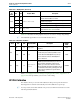
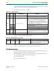
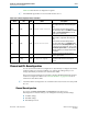
Streamer Module
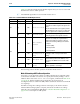
The Streamer module defines the following two modes for channel and PLL
reconfiguration:
■ Mode 0—MIF. Uses a memory initialization file (.mif) to reconfigure settings.
■ Mode 1—Direct Write. Uses a series of Avalon-MM writes on the reconfiguration
management interface to change settings. Table 10–9 lists the Streamer’s
memory-mapped registers that you can access using Avalon-MM read and write
commands on reconfiguration management interface.
Table 10–21. Channel Reconfiguration Bit Ordering
Number of Lanes
Specified FPGA Fabric Width
(Total Bits)
Default Channel Width
(Total Bits)
Used Bits
1 32 bits (32 bits) 64 bits/lane (64 bits) Lane 0: [31:0]
2 40 bits (80 bits) 64 bits/lane (128 bits)
Lane 0: [39:0]
Lane 1: [103:64]
3 40 bits (120 bits) 64 bits/lane (192 bits)
Lane 0: [39:0]
Lane 1: [103:64]
Lane 2: [167:128]