
User guide

Chapter 10: Transceiver Reconfiguration Controller 10–19
PLL Reconfiguration
March 2012 Altera Corporation Altera Transceiver PHY IP Core
User Guide
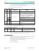
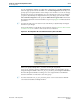
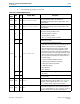
You can establish the number of possible PLL configurations on the Reconfiguration
tab of the appropriate transceiver PHY IP core. The Reconfiguration tab allows you to
specify up to five input reference clocks and up to four TX PLLs. You can also change
the input clock source to the CDR PLL; up to five input clock sources are possible. If
you plan to dynamically reconfigure the PLLs in your design, you must also enable
Allow PLL Reconfiguration and specify the Main TX PLL logical index which is the
PLL that the Quartus II software instantiates at power up. Figure 10–4 illustrates these
parameters.
1 You must provide your own custom reset controller if you dynamically reconfigure
the PLLs in your design.
For more information on the Stratix V reset sequence, refer to Transceiver Reset Control
in Stratix V Devices in volume 3 of the Stratix V Device Handbook.
When you specify multiple PLLs, you must use the QSF assignment,
XCVR_TX_PLL_RECONFIG_GROUP
, to identify the PLLs within a reconfiguration group
using the Assignment Editor. The
XCVR_TX_PLL_RECONFIG_GROUP
assignment identifies
PLLs that the Quartus II Fitter can merge. You can assign TX PLLs from different
transceiver PHY IP core instances to the same group.
1 You must create the
XCVR_TX_PLL_RECONFIG_GROUP
even if one transceiver PHY IP
core instance instantiates multiple TX PLLs.
Figure 10–4. Reconfiguration Tab of Custom and Low Latency Transceiver PHYs