
User guide


10–12 Chapter 10: Transceiver Reconfiguration Controller
EyeQ
Altera Transceiver PHY IP Core March 2012 Altera Corporation
User Guide
f Refer to the DC and Switching Characteristics for Stratix V Devices in the Stratix V Device
Handbook for the correspondence between the value specified by the reconfiguration
data and the actual values that result from these assignments. The actual values are
currently pending characterization of Stratix V silicon.
1 All undefined register bits are reserved and must be set to 0.
Refer to “Changing Transceiver Settings Using Register-Based Reconfiguration” on
page 10–27 and “Changing Transceiver Settings Using Streamer-Based
Reconfiguration” on page 10–28 for the procedures you can use to update PMA
settings.
f Refer to Application Note 645: Dynamic Reconfiguration of PMA Controls in Stratix V
Devices for an example demonstrating the use of the Transceiver Reconfiguration
Controller.
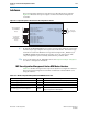
EyeQ
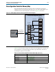
EyeQ is a debug and diagnostic tool that analyzes the incoming data, including the
receiver’s gain, noise level, and jitter after the receive buffer.
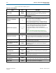
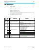
Table 10–10. PMA Offsets and Values
Offset Bits R/W Register Name Description
0x0 [6:0] RW V
OD
V
OD.
The following encodings are defined:
■ 6’b000000:6’b111111:0–63
0x1 [5:0] RW
Pre-emphasis pre-tap
The following encodings are defined:
■ 5’b00000–5’b10000: 0
■ 5’b00001–5’b01111: -15 to -1
■ 5’b10001–5b’11111: 1 to 15
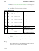
0x2 [5:0] RW
Pre-emphasis first post-tap
The following encodings are defined:
■ 5’b00000–5’b11111: 0–31
0x3 [5:0] RW
Pre-emphasis second post-tap
The following encodings are defined:
■ 5’b00000–5’b10000: 0
■ 5’b00001–5’b01111: -15 to -1
■ 5’b10001–5b’11111: 1 to 15
0x10 [3:0] RW
RX equalization DC gain
The following encodings are defined:
■ 3’b000–3b’111 :0–4
0x11 [3:0] WO
RX equalization control
The following encodings are defined:
■ 4’b0000–4’b1111: 0–15
0x20 [0] WO
Pre-CDR Reverse Serial
Loopback
Writing a 1 to this bit enables S reverse
serial loopback. Writing a 0 disables pre-
CDR reverse serial loopback.
0x21 [0] WO
Post-CDR Reverse Serial
Loopback
Writing a 1 to this bit enables post-CDR
reverse serial loopback. Writing a 0
disables post-CDR reverse serial loopback.