
User guide


Chapter 10: Transceiver Reconfiguration Controller 10–9
Reconfiguration Controller Memory Map
March 2012 Altera Corporation Altera Transceiver PHY IP Core
User Guide
Reconfiguration Controller Memory Map
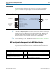
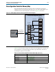
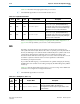
This section describes the memory map that control reconfiguration and signal
integrity features. Each register-based feature has its own Avalon-MM address space
within the Transceiver Reconfiguration Controller as Figure 10–3 illustrates.
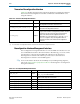
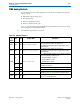
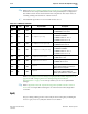
Table 10–8 lists the address range for the Transceiver Reconfiguration Controller and
the reconfiguration and signal integrity modules. It provides links to the sections
describing the registers in each module.
Figure 10–3. Memory Map of the Transceiver Reconfiguration Controller Registers
Direct Addressing
Address Offset
0x00
0x13
0x0B
0x1B
0x2B
0x33
0x3B
0x43
0x7F
Transceiver Reconfiguration Controller
Avalon-MM Interface
reconfig_mgmt_*
Avalon-MM
Registers
Signal Integrity
Features
DFE
ADCE
AT X
Tuning
MIF
Streamer
PLL
Reconfig
EyeQ
PMA
Analog
EyeQ
. . .
DFE
. . .
PMA
ADCE
. . .
AT X
. . .
Streamer
. . .
PLL
. . .
SM
Embedded
Controller
. . .
Table 10–8. Transceiver Reconfiguration Controller Address Map (Part 1 of 2)
Address Link
7’h08–7’h0C “PMA Analog Controls” on page 10–11
7’h10–7’h14 “EyeQ” on page 10–12
7’h18–7’h1C “DFE” on page 10–14
7’h28–7’h2C “AEQ” on page 10–16
7’h30–7’h34 “ATX PLL Calibration” on page 10–17