
User guide


Chapter 9: Deterministic Latency PHY IP Core 9–23
Channel Placement and Utilization
March 2012 Altera Corporation Altera Transceiver PHY IP Core
User Guide
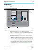
Although you must initially create a separate reconfiguration interface for each
channel and TX PLL in your design, when the Quartus II software compiles your
design, it reduces the number of reconfiguration interfaces by merging
reconfiguration interfaces. The synthesized design typically includes a
reconfiguration interface for three channels. Allowing the Quartus II software to
merge reconfiguration interfaces gives the Fitter more flexibility in placing transceiver
channels.
Table 9–19 describes the signals in the reconfiguration interface. This interface uses
the Avalon-MM PHY Management interface clock.
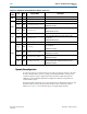
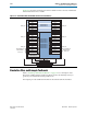
Channel Placement and Utilization
The Deterministic Latency PHY IP core has the following restriction on channel
placement:
■ Channels 0–2 in transceiver banks GXB_L0 and GSB_R0 of Arria V devices are not
available for deterministic latency protocols.
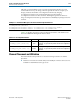
Example 9–1. Informational Messages for the Transceiver Reconfiguration Interface
PHY IP will require 2 reconfiguration interfaces for connection to the external
reconfiguration controller.
Reconfiguration interface offset 0 is connected to the transceiver channel.
Reconfiguration interface offset 1 is connected to the transmit PLL.
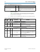
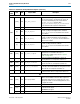
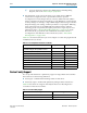
Table 9–19. Reconfiguration Interface
Signal Name Direction Description
reconfig_to_xcvr [(<n>70)-1:0]
Sink
Reconfiguration signals from the Transceiver Reconfiguration
Controller. <n> grows linearly with the number of reconfiguration
interfaces.
reconfig_from_xcvr[(<n>46)-1:0]
Source
Reconfiguration signals to the Transceiver Reconfiguration
Controller. <n> grows linearly with the number of reconfiguration
interfaces.