
User guide

9–16 Chapter 9: Deterministic Latency PHY IP Core
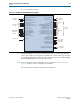
Interfaces
Altera Transceiver PHY IP Core March 2012 Altera Corporation
User Guide
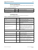
Avalon-ST TX Input Data from the MAC
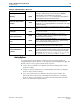
Table 9–11 describes the signals in the Avalon-ST input interface. These signals are
driven from the MAC to the PCS. This is an Avalon sink interface.
f For more information about the Avalon-ST protocol, including timing diagrams, refer
to the Avalon Interface Specifications.
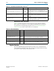
Avalon-ST RX Output Data to the MAC
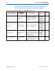
Table 9–12 describes the signals in the Avalon-ST output interface. These signals are
driven from the PCS to the MAC. This is an Avalon source interface
Clock Interface
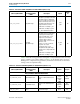
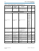
Table 9–13 describes clocks for the Deterministic Latency PHY. The input reference
clock,
pll_ref_clk
, drives a PLL inside the PHY-layer block, and a PLL output clock,
rx_clkout
is used for all data, command, and status inputs and outputs.
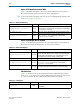
Table 9–11. Avalon-ST TX Interface
Signal Name Direction Description
tx_parallel_data[(<n><w>)-1:0]
Sink
This is TX parallel data driven from the MAC. The ready latency on
this interface is 0, so that the PHY must be able to accept data as
soon as it comes out of reset.
tx_clkout[<n>-1:0]
Output This is the clock for TX parallel data, control, and status signals.
tx_datak[(<n>(<d>/<s>)-1:0]
Sink
Data and control indicator for the received data. When 0, indicates
that
tx_parallel_data
is data, when 1, indicates that
tx_parallel_data
is control.
Table 9–12. Avalon-ST RX Interface
Signal Name Direction Description
rx_parallel_data[(<n><d>)-1:0]
Source
This is RX parallel data driven from the Deterministic Latency PHY
IP core. The ready latency on this interface is 0, so that the MAC
must be able to accept data as soon as the PHY comes out of
reset. Data driven from this interface is always valid.
rx_clkout[<n>-1:0]
Output This is the clock for the RX parallel data source interface.
rx_datak[(<n>(<d>/<s>)-1:0]
Source
Data and control indicator for the source data. When 0, indicates
that
rx_parallel_data
is data, when 1, indicates that
rx_parallel_data
is control.
rx_runningdisp[(<n>(<d>/<s>)-1:0]
Source This status signal indicates the disparity of the incoming data.
Table 9–13. Clock Signals
Signal Name Direction Description
pll_ref_clk
Input
Reference clock for the PHY PLLs. Frequency range is
60–700 MHz.