
User guide


Chapter 8: Low Latency PHY IP Core 8–3
Parameter Settings
March 2012 Altera Corporation Altera Transceiver PHY IP Core
User Guide
Parameter Settings
To configure the Low Latency PHY IP core in the MegaWizard Plug-In Manager, click
Installed Plug-Ins > Interfaces > Transceiver PHY > Low Latency PHY v11.1. For
more information about using the MegaWizard Plug-In Manager refer to Chapter 2,
Getting Started.
General Options
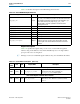
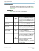
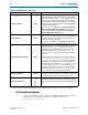
Table 8–3 lists the settings available on General Options tab.
Table 8–3. General Options
Name Value Description
Device family Stratix V This IP core is only available for Stratix V.
Datapath type
Standard
10G
GT
The Low Latency PHY IP core is part of a Standard, 10G, or GT
datapath. In most cases the FPGA fabric transceiver interface
width determines the bandwidth of the datapath; however, when
the FPGA fabric transceiver interface width is 32 or 40 bits, you
have the option of using either the Standard datapath which is
the default mode, or changing to the 10G datapath by selecting
this option. Refer to Table 8–4 for a comprehensive list of
datapath support.
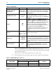
Mode of operation
Duplex
RX
TX
Specifies the mode of operation as Duplex, RX, or TX mode.
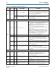
Number of lanes
1
-
32
1–4
Specifies the total number of lanes in each direction. Stratix V
devices include up to 32 GX channels (Standard or 10G) and up
to 4 GT channels. You must instantiate each GT channel in a
separate Low Latency PHY IP core instance. You cannot specify
both GX and GT channels within the same instance.
Enable lane bonding On/Off
When enabled, the PMA uses the same clock source for up to 6
channels in a transceiver bank, reducing clock skew. This option
is only available for the Standard datapath.
Turn this option Off if you are using multiple TX PLLs in a single
Low Latency PHY IP core instance.
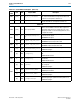
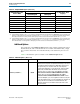
Bonding mode
×N
fb_compensation
Select ×N to use the same clock source for up to 6 channels in a
single transceiver bank, resulting in reduced clock skew. You
must use contiguous channels when you select ×N bonding. In
addition, you must place logical channel 0 in either physical
channel 1 or 4. Physical channels 1 and 4 are indirect drivers of
the ×N clock network.
Select fb_compensation (feedback compensation) to use the
same clock source for multiple channels across different
transceiver banks to reduce clock skew.
For more information about bonding, refer to “Bonded Channel
Configurations Using the PLL Feedback Compensation Path” in
Transceiver Clocking in Stratix V Devices in volume 3 of the
Stratix V Device Handbook.