
User guide


Chapter 7: Custom PHY IP Core 7–21
Interfaces
March 2012 Altera Corporation Altera Transceiver PHY IP Core
User Guide
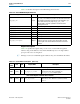
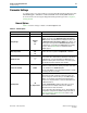
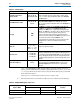
Table 7–20 describes the signals in the PHY Management interface.
Register Descriptions
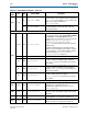
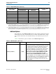
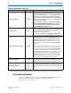
Table 7–21 specifies the registers that you can access over the PHY management
interface using word addresses and a 32-bit embedded processor. A single address
space provides access to all registers.
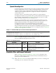
1 Writing to reserved or undefined register addresses may have undefined side effects.
Table 7–20. Avalon-MM PHY Management Interface
Signal Name Direction Description
phy_mgmt_clk
Input
Avalon-MM clock input. There is no frequency restriction for the
phy_mgmt_clk
; however, if you plan to use the same clock for the
PHY management interface and transceiver reconfiguration, you
must restrict the frequency range of
phy_mgmt_clk
to
100–125 MHz to meet the specification for the transceiver
reconfiguration clock.
phy_mgmt_clk_reset
Input Global reset signal. This signal is active high and level sensitive.
phy_mgmt_address[8:0]
Input 9-bit Avalon-MM address.
phy_mgmt_writedata[31:0]
Input Input data.
phy_mgmt_readdata[31:0]
Output Output data.
phy_mgmt_write
Input Write signal.
phy_mgmt_read
Input Read signal.
phy_mgmt_waitrequest
Output
When asserted, indicates that the Avalon-MM slave interface is
unable to respond to a read or write request. When asserted,
control signals to the Avalon-MM slave interface must remain
constant.
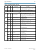
Table 7–21. Custom PHY IP Core Registers (Part 1 of 3)
Word
Addr
Bits R/W Register Name Description
PMA Common Control and Status Registers
0x022 [31:0] R
pma_tx_pll_is_locked
Bit[P] indicates that the TX/CMU PLL (P) is locked to the
input reference clock. There is typically one
pma_tx_pll_is_locked
bit per system.
Reset Control Registers–Automatic Reset Controller
0x041 [31:0] RW
reset_ch_bitmask
Reset controller channel bitmask for digital resets. The
default value is all 1s. Channel <
n
> can be reset when
bit<
n
> = 1.