
User guide

7–18 Chapter 7: Custom PHY IP Core
Interfaces
Altera Transceiver PHY IP Core March 2012 Altera Corporation
User Guide
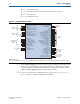
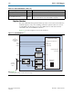
Clock Interface
Table 7–16 describes optional and required clocks for the Custom PHY. The input
reference clock,
pll_ref_clk
, drives a PLL inside the PHY-layer block, and a PLL
output clock,
rx_clkout
(described in Table 7–15 on page 7–17) is used for all data,
command, and status inputs and outputs.
Transceiver Serial Data Interface
Table 7–17 describes the differential serial data interface and the status signals for the
RX interface.
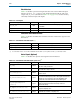
Status Signals (Optional)
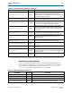
Table 7–18 describes the optional status signals for the RX interface.
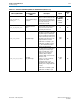
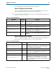
Table 7–16. Clock Signals
Signal Name Direction Description
pll_ref_clk
Input
Reference clock for the PHY PLLs. Frequency range is
50–700 MHz.
rx_coreclkin[<n>-1:0]
Input This is an optional clock to drive the coreclk of the RX PCS.
tx_coreclkin[<n>-1:0]
Input This is an optional clock to drive the coreclk of the TX PCS
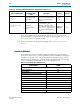
Table 7–17. Serial Interface and Status Signals
(1)
Signal Name Direction Signal Name
rx_serial_data[<n>-1:0]
Input Receiver differential serial input data.
tx_serial_data[<n>-1:0]
Output Transmitter differential serial output data.
Note to Table 7–17:
(1) <n> is the number of lanes. <w> is the PCS to FPGA fabric interface width. <s> is the symbol size in bits. <p> is the number of PLLs.
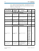
Table 7–18. Serial Interface and Status Signals (Part 1 of 2)
(1)
Signal Name Direction Signal Name
tx_ready
Output
When asserted, indicates that the TX interface has exited the reset
state and is ready to transmit.
rx_ready
Output
When asserted, indicates that the RX interface has exited the
reset state and is ready to receive.
pll_locked[<p>-1:0]
Output
When asserted, indicates that the PLL is locked to the input
reference clock.
tx_forceelecidle[<n>-1:0]
Input
When asserted, enables a circuit to detect a downstream receiver.
It is used for the PCI Express protocol. This signal must be driven
low when not in use because it causes the TX PMA to enter
electrical idle mode and tristate the TX serial data signals.
tx_bitslipboundaryselect
[<n>5-1:0]
Input
This signal is used for bit slip word alignment mode. It selects the
number of bits that the TX block must slip to achieve a
deterministic latency.
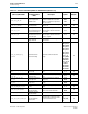
rx_disperr[<n>(<w>/<s>)-1:0]
Output
When asserted, indicates that the received 10-bit code or data
group has a disparity error.
rx_errdetect[<n>(<w>/<s>)-1:0]
Output
When asserted, indicates that a received 10-bit code group has
an 8B/10B code violation or disparity error.