
User guide

7–4 Chapter 7: Custom PHY IP Core
Parameter Settings
Altera Transceiver PHY IP Core March 2012 Altera Corporation
User Guide
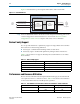
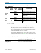
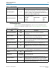
PCS-PMA interface width 8, 10, 16, 20
The PCS-PMA interface width depends on the FPGA fabric
transceiver interface width and whether 8B/10B is enabled. The
following combinations are available:
FPGA/XCVR 8B/10B PCS-PMA Interface Width
8No8
8Yes10
10 No 10
16 No 8 or 16
16 Yes 10 or 20
20 No 10 or 20
32 No 16
32 Yes 20
40 No 20
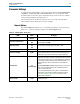
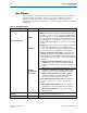
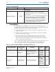
PLL type
CMU
ATX
You can select either the CMU or ATX PLL. The CMU PLL has a
larger frequency range than the ATX PLL. The ATX PLL is designed
to improve jitter performance and achieves lower channel-to-
channel skew; however, it supports a narrower range of data rates
and reference clock frequencies. Another advantage of the ATX PLL
is that it does not use a transceiver channel, while the CMU PLL
does.
Because the CMU PLL is more versatile, it is specified as the
default setting. An informational message displays in the message
pane telling you whether the chosen settings for Data rate and
Input clock frequency are legal for the CMU PLL, or for both the
CMU and ATX PLLs.
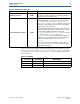
Data rate 622–11000 Mbps Specifies the data rate.
Base dat
a rate
1 × Lane rate
2 × Lane rate
4 × Lane rate
The base data rate is the frequency of the clock input to the PLL.
Select a base data rate that minimizes the number of PLLs
required to generate all the clocks required for data transmission.
By selecting an appropriate base data rate, you can change data
rates by changing the divider used by the clock generation block.
For higher frequency data rates 2 × and 4× base data rates are not
available.
Input clock frequency Variable
Specifies the frequency of the PLL input reference clock. The
frequency required is the Base data rate/2. You can use any Input
clock frequency that allows the PLLs to generate this frequency.
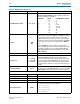
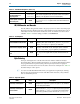
Additional Options
Enable TX Bitslip On/Off When enabled, the TX bitslip word aligner is operational.
Create rx_coreclkin port On/Off This is an optional clock to drive the coreclk of the RX PCS
Create tx_coreclkin po
rt On/Off This is an optional clock to drive the coreclk of the TX PCS
Create rx_recovered_clk port On/Off When enabled, the RX recovered clock is an output.
Create optional ports On/Off
When you turn this option on, the following signals are added to
the top level of your transceiver for each lane:
■
tx_forceelecidle
■
rx_is_lockedtoref
■
rx_is_lockedtodata
■
rx_signaldetect
Table 7–3. General Options (Part 2 of 3)
Name Value Description