
User guide

Chapter 7: Custom PHY IP Core 7–3
Parameter Settings
March 2012 Altera Corporation Altera Transceiver PHY IP Core
User Guide
Parameter Settings
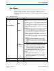
To configure the Custom PHY IP core in the parameter editor, click Installed Plug-Ins
> Interfaces > Transceiver PHY > Custom PHY v11.1. You can use the tabs on the
parameter editor to select the options required for the protocol. Presets are available
for the 1.25 Gbps Ethernet (1.25GbE) protocol.
The following sections describe all of the options on seven tabs of the parameter
editor and then list parameters that are set for 1.25GbE.
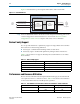
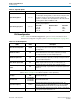
General Options
The General Options tab allows you to set the basic parameters of your transceiver
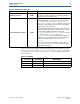
PHY. Table 7–3 lists the settings available on the General Options tab.
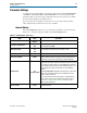
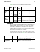
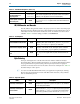
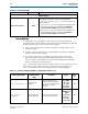
Table 7–3. General Options (Part 1 of 3)
Name Value Description
Device family
Arria V
Stratix V
Specifies the device family. Arria V and Stratix V are available.
Parameter validation rules
Custom
GbE
Allows you to specify the transceiver protocol. Select Custom if you
are not implementing GbE.
Mode of operation
Duplex
TX
RX
You can select to transmit data, receive data, or both.
Number of lanes 1–32 The total number of lanes in each direction.
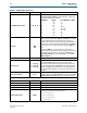
Enable lane bonding On/Off
When enabled, a single clock drives multiple lanes, reducing clock
skew. In Stratix V devices, up to 6 lanes can be bonded if you use
an ATX PLL; 5 lanes can be bonded If you select the CMU PLL.
Bonding mode
×N
fb_compensation
Select ×N to use the same clock source for up to 6 channels in a
single transceiver bank, resulting in reduced clock skew. You must
use contiguous channels when you select ×N bonding. In addition,
you must place logical channel 0 in either physical channel 1 or 4.
Physical channels 1 and 4 are indirect drivers of the ×N clock
network.
Select fb_compensation (feedback compensation) to use the same
clock source for multiple channels across different transceiver
banks to reduce clock skew.
For more information about bonding, refer to “Bonded Channel
Configurations Using the PLL Feedback Compensation Path” in
Transceiver Clocking in Stratix V Devices in volume 3 of the
Stratix V Device Handbook.
FPGA fabric transceiver
interface width
8,10,16,20,
32,40
Specifies the total serialization factor, from an input or output pin to
the MAC-layer logic.