
User guide

Chapter 6: Board Test System 6–3
Running the Board Test System
September 2010 Altera Corporation Cyclone III FPGA Development Kit User Guide
3. Set the PGM CONFIG SELECT rotary switch (SW5) to position 1.
4. Turn the power to the board on. The board loads the design stored in the user
hardware 1 portion of flash memory into the FPGA. If your board is still in the
factory configuration or if you have downloaded a newer version of the Board Test
System to flash memory through the Board Update Portal, the design that loads
tests accessing the GPIO, SRAM, and flash memory.
c To ensure operating stability, keep the USB cable connected and the board
powered on when running the demonstration application. The application
cannot run correctly unless the USB cable is attached and the board is on.
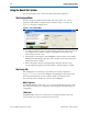
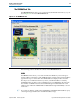
Running the Board Test System
To run the application, navigate to the <install
dir>\kits\cycloneIII_3c120_dev\examples\board_test_system directory and run
the BoardTestSystem.exe application.
1 On Windows, click Start > All Programs > Altera > Cyclone III FPGA Development
Kit <version> > Board Test System to run the application.
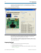
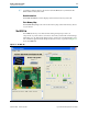
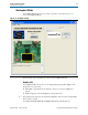
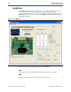
A GUI appears, displaying the application tab that corresponds to the design running
in the FPGA. The Cyclone III FPGA development board’s flash memory ships
preconfigured with the design that corresponds to the Config, GPIO, SRAM&Flash
tabs.
1 If you power up your board with the PGM CONFIG SELECT rotary switch (SW5) in a
position other than position 1, or if you load your own design into the FPGA with the
Quartus II Programmer, you receive a message prompting you to configure your
board with a valid Board Test System design. Refer to “The Configure Menu” for
information about configuring your board.