
User guide

September 2010 Altera Corporation Cyclone III FPGA Development Kit User Guide
5. Board Update Portal
Introduction
The Cyclone III FPGA Development Kit ships with the Board Update Portal design
example stored in the factory portion of the flash memory on the board. The design
consists of a Nios II embedded processor, an Ethernet MAC, and an HTML web
server.
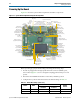
When you power up the board with the PGM CONFIG SELECT rotary switch (SW5)
in position 0, the Cyclone III FPGA configures with the Board Update Portal design
example. The design can obtain an IP address from any DHCP server and serve a web
page from the flash on your board to any host computer on the same network. The
web page allows you to upload new FPGA designs to the FPGA design 1 and design 6
(HW1 and SW1) portion of flash memory, and provides links to useful information on
the Altera website, including links to kit-specific and design resources.
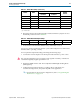
1 After successfully updating the FPGA design 1 and design 6 (HW1 and SW1)flash
memory, you can load the user design from flash memory into the FPGA. To do so, set
the PGM CONFIG SELECT rotary switch (SW5) to position 1 and power cycle the
board.
The source code for the Board Update Portal design resides in the <install
dir>\kits\cycloneIII_3c120_dev\examples directory. If the Board Update Portal is
corrupted or deleted from the flash memory, refer to “Restoring the Factory Design to
the Flash Device” on page A–6 to restore the board with its original factory contents.
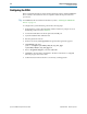
Connecting to the Board Update Portal Web Page
This section provides instructions to connect to the Board Update Portal web page.
1 Before you proceed, ensure that you have the following:
■ A PC with a connection to a working Ethernet port on a DHCP enabled network.
■ A separate working Ethernet port connected to the same network for the board.
■ The Ethernet and power cables that are included in the kit.
To connect to the Board Update Portal web page, perform the following steps:
1. With the board powered down, set the PGM CONFIG SELECT rotary switch
(SW5) to position 0.
2. Attach the Ethernet cable from the board to your LAN.
3. Power up the board. The board connects to the LAN’s gateway router, and obtains
an IP address. The LCD on the board displays the IP address.
4. Launch a web browser on a PC that is connected to the same network, and enter
the IP address from the LCD into the browser address bar. The Board Update
Portal web page appears in the browser.