
Wireless Speaker System User Guide


6
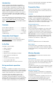
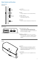
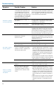
Transmitter Base
Front Panel
1
STANDBY / ON
Switches the power mode between Standby and On for
the transmitter base. This light (left of the STANDBY key)
illuminates when the transmitter base is on.
2
SYNC 1 LED
Illuminates to indicate that the transmitter base is
synchronized with one wireless speaker unit.
3
SYNC 2 LED
Illuminates when two or more M812 wireless speaker
units are connected and synchronized with the
transmitter base. Any speaker that is synchronized can
control the system.
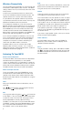
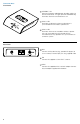
Rear Panel
1
AUX
Connect auxiliary devices (e.g., portable CD players) to
3.5 mm stereo, line-level input jack using supplied cable.
2
FM
Connect the supplied 75 Ohm FM “T” antenna.
3
9VDC
Connect the supplied 9V DC/1.6A wall adapter. Connect
only the adapter supplied with the M812.
1
2
3
1
2
3