Measure what you see.
micro-gloss Manual Patent pending BYK-Gardner GmbH Lausitzer Str. 8 D-82538 Geretsried Germany Tel. 0-800-gardner (0-800-4273637) +49-8171-3493-0 Fax +49-8171-3493-140 260 020 398 E 1008 BYK - Gardner USA 9104 Guilford Road Columbia, MD 21046 USA Phone 800-343-7721 301-483-6500 Fax 800-394-8215 301-483-6555 www.byk.
Dear customer, thank you for having decided for a BYK-Gardner product. BYK-Gardner is committed to providing you with quality products and services. We offer complete system solutions to solve your problems in areas of gloss and physical properties. As the basis of our worldwide business, we strongly believe in total customer satisfaction.
Table of content 1. System description and Delivery notes ............................................ 7 2. Power supply ..................................................................................... 9 2.1 Power supply battery-operated .................................................................. 9 2.2 Changing the battery ................................................................................. 10 2.3 External power supply ........................................................
Table of content 7.2.3 Exit block ..................................................................................................... 30 8.2.4 Delete block ................................................................................................ 30 8.2.5 Delete measurement ................................................................................. 30 7.3 Continuous ........................................................................................ 31 7.4 Basic mode .....................
Table of content 12. Interface ............................................................................................ 44 12.1 Installation .................................................................................................. 45 13. Standards .......................................................................................... 46 14. Technical data .................................................................................. 48 15. Errors and warning messages ...................
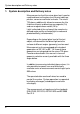
System description and Delivery notes 1. System description and Delivery notes Measurement units of the micro-gloss family can be used to determine the gloss level of paint coatings, plastics, ceramics and metal surfaces. The microTRI-gloss µ additionally allows to measure the film thickness of paint and coatings on magnetic (Fe) and non-magnetic base metals (NFe). Light is directed at the surface of the sample at a defined angle and the reflected light is measured photoelectrically (reflectometer).
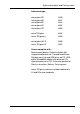
System description and Delivery notes Instrument type: micro-gloss 20° micro-gloss 60° micro-gloss 85° micro-gloss 45° micro-gloss 75° 4440 4442 4444 4454 4456 micro-TRI-gloss micro-TRI-gloss µ 4446 4448 micro-gloss 60° S micro-TRI-gloss S 4450 4452 Comes complete with: Measurement device, Protective holder with integrated calibration tile, Traceable certificate, Software easy-link and USB driver on CD, USBcable, Bluetooth® adapter with driver on CD, Operating manual on CD, Quick user guide and Safety
System description and Delivery notes Recommended accessories: Checking standards for control of test equipment 8 for micro-gloss 20° for micro-gloss 60° for micro-gloss 85° for micro-gloss 45° for micro-gloss 75° 4422 4462 4487 4458 4459 for micro-TRI-gloss and micro-TRI-gloss µ 4434 micro-gloss 60° S micro-TRI-gloss S 4464 4438 mirror type, highly reflective for 20°, 60° and 85° 4433
Power supply 2. Power supply Before operating the instrument for the first time, please read the operating instructions and pay attention to the safety instructions in Chapter 1. Unpack the device and check to make certain all pieces have been included with delivery (for scope of delivery, see Section Delivery notes). 2.1 Power supply battery-operated The battery must be placed in the measuring unit for operation service. The device runs on one AA 1.5-V alkaline or 1.2-V NiMH rechargeable battery.
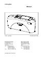
Power supply 2.2 Changing the battery To insert or change the battery open the battery compartment. The easiest way to do this is by turning the cover with a coin one-eighth of a rotation to the left. Turn the device back around and allow the old battery and the battery compartment cover to slide into your hand. Changing the battery Insert the new battery with the positive (top) end first into the battery compartment and set the battery compartment cover in place again.
Controls 3.
Controls The basic system consists of the measuring device and the protective holder. The protective holder is used for calibration and to store the measurement unit. Calibration is performed inside the holder automatically at the touch of a button. The gloss standard required for this purpose is kept in the holder and is positioned in such a manner that calibration is always performed at the same point. When the device is turned on inside the holder, it performs a self-test (autodiagnosis).
Getting started 4. Getting started 4.1 Turning on the unit and measuring To turn on the unit, press the mode scroll wheel. Information on the date and last certification appears in the display. If the device was turned on in its holder, the autodiagnosis test is performed (see the section on Calibration). Then the unit switches into the last measurement mode to be selected. Pressing operate initiates measurements.
Getting started 4.2 Navigation All control functions are controlled by the mode scroll wheel. Pressing the wheel causes a menu to appear in the display. Turning the wheel allows you to move the black mark to the desired function and to select or activate it by pressing the wheel. What functions are displayed in the menu depends on the settings in the main menu. The main menu is the “central” level and can always be reached quickly.
Getting started 4.3 Change names/numbers For some functions, you can enter or change the date or name. The arrow pointing upward marks the position that can be changed. To change the character, turn the scroll wheel. When you press the wheel, the arrow jumps to the next character. After you have adjusted the last character or number, confirm your input by pressing the wheel. When you enter the name, the arrow jumps to the first character. This allows you to correct any inadvertent incorrect entries.
Getting started 4.4 Overview of main menu Mode Sample mode Statistics Continous Basic mode Advanced mode Measurement without statistical evaluation. Multiple measurement with statistics. Continuous measuring with adjustable interval. Measuring without statistics, saving and difference. Reactivates all menues and functions when Basic mode was activated. Geometry/Sensor Select geometry and thickness sensor if applicable.
Calibrate 5. Calibrate The holder with the integrated glass standard is used for calibration. Always keep the measurement unit in the holder. This protects the measurement optics and ensures that the standard is always at hand. If you have several devices of this type, you must put the unit in the holder which belongs to the unit (see the serial number). Make certain that the standard is clean and there are no cracks on it.
Calibrate 5.2 Calibrate You should recalibrate the device if ambient conditions have changed. This applies especially when changing location if major changes in temperature and relative humidity may be expected as a result (for example inside/outside). When moving from cold areas to warm areas, there is a danger of condensation.
Calibrate After the zero setting has been performed, the display AIR will appear. To proceed with this, hold the instrument in midair and press the operate button. The successful calibration is confirmed in the display (OK). The instrument returns to the selection menu Calibration. Note: The film thickness measurement is also influenced by the basis metal. It is therefore advisable to perform the zero calibration on the uncoated metal which is used for the object to be measured.
Calibrate A warning message appears. You can cancel this process by pressing the operate button. If you press the scroll wheel, you will continue with the process of changing calibration values. In the next display you can enter new calibration values. After you have entered the new value, a warning message appears again in the display. You can again abort the process with operate. If you confirm the new value by pressing the scroll wheel, the value will be accepted.
Calibrate You can set the scales of the measurement values for gloss and thickness separately. 5.2.5 Scale Gloss You can use the Scale menu option to switch back and forth between Gloss Units and Reflectance (see the Section on Practical measuring suggestions). Move the mark to the desired entry and press mode. A check mark identifies the Scale that is selected. After you switch the Scale, the unit must not be recalibrated. 5.2.
Calibrate 5.3 Calibrating standards To ensure exact calibration, only original standards from the manufacturer should be used. These are calibrated against tested primary standards. Their surface must not be touched and must be protected against scratches. Due to environmental influences, however, the values of standards can change over the course of time even if they are handled gently.
Measurement techniques 6. Measurement techniques In accordance with the standard, the reflectometer value is related to a black glass standard at a defined index of refraction (generally 1.567) which is thus equal to 100 units. Reflectometers are differentiated by the angle of incidence of the illuminating mechanism. Geometries are set in the standards at 20°, 60° and 85°. 6.
Measurement techniques 6.2 Anodized aluminum and other metal surfaces The measuring unit is equipped with an extended measuring range for measuring samples with a very high reflectance. The reflectance of non-metallic surfaces increases with the angle of incidence. The reflective properties of metals do not always behave in this manner. Because of double reflection, the light is partially reflected on the coating and partially on the metal underneath.
Measurement techniques 6.3 Measurement of film thickness The film thickness sensor functions according to the magnetic method (Fe) or the eddy current method (NFe). Therefore, the measurement results can be distorted by strong magnetic fields or electromagnetic radiation. The measurement of film thickness is influenced by the thickness and magnetic (Fe) or electrical (NFe) properties of the basis metal.
Measurement Modes 7. Measurement Modes You can select different types of measurement in the Mode menu. The mode that is activated is identified by a check mark. 7.1 Sample mode Single measurements can be performed without statistical evaluation in Sample mode. The results can be saved and compared with a standard (refer to Memory or Difference). When Memory is turned on, a name is suggested after every measurement. You can confirm this name directly or change it.
Measurement Modes 7.2 Statistics You can make multiple measurements with each sample in Statistics mode. These measurements will be evaluated statistically and displayed. The results can be saved and compared with a standard. These functions must be previously activated (refer to Memory or Difference). When Memory is turned on, a name is suggested after all measurements of a sample (block). You can confirm this name directly or change it.
Measurement Modes Note: (micro-TRI-gloss µ only) When STATISTICS is activated, all film thickness values are stored in the Memory independently of the sonde used. In the case of an incorrect substrate or a high film thickness, “Infi“ is written to the memory. When the instrument is switched off, the last setting remains active. 7.2.1Number of measurements You can adjust the number of measurements per sample or per block with this option, from 2 - 99.
Measurement Modes 7.2.2Display In the Statistics measurement display, you can assign the following data freely to three columns: Value: Last value to be measured Mean value: Arithmetic mean of the sample (block). Maximum: Highest measurement value of the sample Minimum: Lowest measurement value of the sample Range: The difference between the maximum and minimum value. Std. Dev.: The standard deviation of the sample Difference*: The difference between the sample and a target value.
Measurement Modes 7.2.3Exit block This function terminates the block before it reaches the required number of measurements n. It is useful if you have selected a high number of measurements for n, for example in the case of large samples. If Save is turned on, a display appears to enter a block name for the sample. 8.2.4Delete block This function deletes the current block. 8.2.5Delete measurement This function deletes the last measurement value.
Measurement Modes 7.3 Continuous You can use this function to perform up to 99 measurements at an adjustable measurement interval. This is helpful when you are covering large samples and you want to evaluate the homogeneity of the surface. Activate Continuous under Mode from the Main menu. A screen appears for starting a new sequence. To start the measurement, press operate. The unit now performs measurements up to 99 times at the set interval.
Measurement Modes The measuring interval can be changed before a sequence is started. Therefore press the mode wheel to open the Continuous submenu. The longest measurement interval possible is 9 seconds, the shortest 0 seconds for continous measuring. The interval slightly increases when thickness sensor is activated. 7.4 Basic mode The selection options are limited to the most essential in Basic mode. This also greatly simplifies operation in this mode.
Geometry/Sensor 8 Geometry/Sensor In this menu, you can select the geometry for the gloss measurement, just as the sensor for the film thickness measurement (at micro-TRI-gloss µ). 8.1 Geometry selection Choose Gloss Geometry from the Geometry/Sensor menu. You can choose between the representation of one, two or all three geometries in the display. The currently set angle combination is indicated in the Geometry menu by a check mark.
Geometry/Sensor Combi When changing the substrate, the sensor will be switched over automatically Choose the desired sensor with the scroll wheel. Press mode to confirm the desired selection. The selected sensor is indicated in the display. Note: The measurement unit can be selected in µm or mil for display (see section Calibration: Scale Thickness). 8.3 Sensor-setting Combi When switching the Thickness setting to Combi, the measurement will be run through in the sequence Fe - NFe.
Memory 9. Memory To save measurement values, you must activate the Memory function before measuring or else select or create a memory. Up to 999 measurements can be stored. A fixed memory area is already created for each geometry or combination (e.g. M60°). These memory areas cannot be deleted. A total of 50 memory areas can be created. The Memory function can be used for sample mode, Statistics and Continuous measurements.
Memory 9.3 Create memory Users can set up their own memory areas with this function. Select the required geometry before you activate this function. Then you must enter the name of a memory area. You can confirm the suggested name directly with the operate button or change it with the scroll wheel. After you confirm, Save is automatically turned on. 9.4 Delete memory This menu lists all memory areas that have been created with the number of values stored in each one.
Memory The values of the first measurement appear in the display. The sample name is displayed in the highlighted field. Turning the wheel switches the display to the next sample with its corresponding values. Which values are displayed in the columns (for example mean value, min., max.) depends on the display currently selected for Statistics.
Difference measurement and Pass/Fail 10. Difference measurement and Pass/Fail You can compare the readings of samples with the value of a previously measured or saved standard. For saved standards, you can also display whether the test specimen falls within the limits (Pass) or outside (Fail). Up to 50 standards can be saved. They are stored in a separate area of memory. For each geometry you can determine: - A target value - Maximum and minimum for Pass/Fail, see Create standard or Change standard. 10.
Difference measurement and Pass/Fail The measured standard values are saved as the target values. At the same time, Difference measurement is turned on and the measured standard is activated. If you want to define limit values additionally , you can use the “Change standard” function. For measuring the samples continue by pressing operate. The display shows the sample values and difference to the target. The Measure standard function can also be reached directly from the measurement screen by pressing mode.
Difference measurement and Pass/Fail 10.4 Create standard Standards can also be saved by entering the target and limit values with the scroll wheel. Move the mark to “Create standard” and activate the function. A display appears in which you must assign a name for the new standard. If you inadvertently select a name that has already been used, a message will appear to this effect and the marker arrow will jump back to the first position of the name. Confirm the name with the operate button.
Difference measurement and Pass/Fail 10.5 Change standard You can use this function to change target values and limit values of saved standards. You can also use it to define limit values subsequently (for example for a measured standard). Use the scroll wheel to move the mark to Change standard and press the wheel. All standards are listed one after the other in the following menu. Select the desired standard and press the scroll wheel.
Setup 11. Setup You can make general settings in the Setup menu, for example Language or Display time. 11.1 Bluetooth® You can use this menu option to turn the Bluetooth® function on or off. Use the scroll wheel to move the mark to Bluetooth® and press the wheel. When Bluetooth® is turned on, a check mark appears at the end of the line. Additionally, the Bluetooth® symbol appears shortly in the start screen when you switch on the instrument. 11.2 Date/Time The unit contains an integrated clock.
Setup 11.5 Language You can use this menu to select the display language. Use the scroll wheel to move the mark to the desired language and press the wheel. 11.6 Info You can use this menu option to find the following information: • Catalog No. • Serial No.
Interface 12. Interface The measurement device is equipped with an interface that allows direct communication with a PC. Measurement data can be transferred from memory or directly after each measurement. The easy-link program is included with delivery for this purpose. The transferred data are displayed immediately in a test report. For data transfer you can use the USB cable included with delivery or the wireless connection via the integrated Bluetooth® module.
Interface 12.1 Installation Bluetooth® : Please refer to the separate Bluetooth® Installation Guide. Software easy-link and USB drivers: Insert the easy-link CD into the CD drive and run the „setup.exe“ for installation of the program. Follow the instructions on the screen. After installation, the default directory of the appropriate Excel Reports will be “...\bykware\easylink“. As you connect the device to the USB port of the computer, it is recognized by the system and the hardware assistant opens: 1.
Standards 13.
Standards ISO 2178 Non-magnetic coatings on magnetic substrates Measurement of coating thickness - Magnetic method ISO 2360 Non-conductive coatings on non-magnetic electrically conductive basis materials. Measurement of coating thickness. Amplitude-sensitive eddy-current method.
Technical data 14. Technical data General technical data Temperature range +15 °C to +40 °C (60°F to 104°F) for operation - 10 °C to +60 °C (-14°F to 140°F) for storage Rel. humidity Up to 85% non-condensing Mearurement unit: Memory 999 measurements with date and time, in up to 50 memory areas Difference measurement Memory for 50 references Interface USB Evaluation software easy-link, included Power supply 1 Mignon Alkaline (AA/LR6) or rechargeable NiMH Battery 1.5VDC, max. 0.1A Rechargeable 1.2VDC, max.
Technical data Film thickness measurement: Substrate Fe: magnetic, e.g. iron NFe: non magnetic, e.g. aluminium Sonde One point Measurement range 0....500 µm (0 … 20 mil) Accuracy ±(1.5µm +2%*) *of measured value Min. substrate thickness Fe: 0.20 mm (8 mil) NFe: 0.05 mm (2 mil) Specifications subject to change without notice.
Errors and warning messages 15. Errors and warning messages Memory full Reference memory full Transfer the content of memory to a PC and then delete the contents of memory. A maximum of 50 references can be saved. It may be necessary to delete old references.
Errors and warning messages Error Thickness Operating error: improper application, raising before measurement is complete, or calibration error. Repeat the procedure. If the error is shown repeatedly despite correct operation and calibration, please contact our customer service department. Please observe the instructions on cleaning standards in the section on Calibration. Fluctuations in measurement values Was the same point on the sample used for all measurements? No.
Cleaning and maintenance 16. Cleaning and maintenance • Do not insert any objects into the measurement aperture for cleaning. The instrument could get damaged - affecting a proper and safe operation. • The instrument housing is resistant to a number of solvents, but cannot be guaranteed to withstand all chemicals. You should therefore use a soft, moist cloth for cleaning. For cleaning excessive dirt, use ethanol or cleaning alcohol.
Service and Certification 17. Service and Certification Service Besides the repair of your instrument we offer the following additional services: First diagnosis on the telephone or by e-mail Call us or send us an e-mail and we will try to solve your problem. If this is not successful, please send us the instrument for repair. Preventive maintenance, calibration, and recertification For precautionary reasons we recommend regular preventive maintenance.
Service and Certification Service Centers for BYK-Gardner products Germany BYK-Gardner GmbH Lausitzer Strasse 8 82538 Geretsried Germany Phone:+49-8171-3493-0 Fax: +49-8171-3493-166 USA BYK-Gardner USA 9104 Guilford Road Columbia, MD 21046 USA Phone:+1-301-483-6500 Fax: +1-301-483-6555 China BYK-Gardner Shanghai Office Room 1407, SIPAI PLAZA 103, Cao Bao Road Shanghai 200233 P.R.
Copyright 18. Copyright This instruction manual is an important part of this instrument. It contains essential information about setting up, placing in service and use. If you pass the device on to another user, please ensure that the instruction manual is included with the instrument. The manual must be studied carefully before working with the equipment. Please contact your regional service office if you have any questions or require additional information about the device.
260 020 398 E 1008