Measure what you see.
Manual Cat. No.: 5405 BYK - Gardner USA 9104 Guilford Road Columbia, MD 21046 USA Phone 800-343-7721 301-483-6500 Fax 800-394-8215 301-483-6555 www.byk.com/instruments BYK-Gardner GmbH Lausitzer Str. 8 D-82538 Geretsried Germany Tel.
English Contents Table of contents 1. Information............................................................................................... 5 2. System Description................................................................................... 7 3. Start-up...................................................................................................... 8 4. Operation................................................................................................ 10 5. Maintenance.............
English Information 1. Warning ! • The instrument must be securely positioned and fastened onto a level bench or table capable of supporting its weight. DO NOT: • use the instrument near water • clean the instrument with solvents (apart from the indenter and clamping system) • open the case.
English Information 1.
English System Description 2. System Description The Cupping Tester was originally designed to assess the resistance of coatings of paints varnishes (and related products) to cracking and/or detachment from the substrate under different conditions of controlled deformation.
English Start-up 3. Start-up Unpacking: Carefully open the packaging, remove the smaller instruments before removing the instrument itself. Make sure all components in the component list are included. Installation: *Prior to installation, keep in mind that the instrument must not be exposed to; excessive heat or humidity, aggressive or corrosive substances, flammable substances, or excessive vibration 1.
5. Slide off the battery cover on the magnifying glass. Insert the four AA cells into the body (see battery orientation indicated on the cover). 6. The magnifier assembly is supplied separately. Slide the magnifier clamp plate onto the body of the magnifier and tighten. Slide the circular shaft through the clamp plate and tighten the clamping knob. Slide the assembly onto the instrument and adjust its position for optimum viewing of the sample. 7.
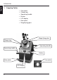
English Operation 4. Operation 1. Rotate the handles [3] clockwise (as viewed from the right-hand side of the instrument) to lower the hemispherical indenter just below the level of the bottom clamping ring [2]. 2. Switch on by pressing the operating button [4]. The LCD [5] will show - - - -, followed by its current position or ZEr0 (if below the zero datum position). Switch on the magnifier light [7], if required. Note that ZEr0 will flash if the indenter is lowered about 0.
English Operation 6. Clamp the substrate in position by turning the handles on the clamping clockwise – hand force is sufficient. 7. There are two methods. Choose one of the two procedures below (8 or 9). 8. Method A – Go/No Go A pre-determined depth of deformation is applied to the substrate in order to test for compliance to a specification. The substrate may or may not fail at the applied depth of deformation.
English Operation 11. Check for any detached coating on the instrument and remove these before starting another test. 12. Turn the handles in a clockwise direction (as viewed from the right-hand side of the instrument) to lower the hemispherical indenter until ZEr0 is shown on the LCD and then reverse direction until 0.00 is shown. The Cupping Tester is now set at the datum position and is ready for the next test. 13.
width and length of at least 70 mm and a thickness range of 0.3mm to 1.25mm (maximum). • Do not exceed the above figures as this may cause permanent damage to the instrument. Operation Notes (cont.) Zero Datum All measurements are taken from the zero datum position (where the indenter is level with the bottom sample clamp-ring). Press the button (at any position) to zero the display.
English Operation LCD Display In operation, the display will show one of the following states – LCD display Status ZEr0 Indenter is below zero or un-zeroed ZEr0 (flashing) Indenter is below the zero position by at least 0.5mm nn.nn Normal distance reading HigH Reading exceeds maximum range OFF Manual power off indication Bat (flashing intermittently) Low Battery.
5. Maintenance The frequency of regular maintenance depends on the degree of use, together with the thickness of the substrates used – • Heavy use – every 3 months • Medium use – every 6 months • Low use – every 12 months 1. Conduct a functional check to ensure that the Clamp Plate is free to rotate, treat the screw threads sparingly with light grease. If the two knobs and attached to the spindles are damaged, they may be replaced. 2.
English Maintenance Maintenance Schedule Between tests Clean the indenter and clamp system as necessary. Daily Check the zero-datum as required. Yearly Have the instrument serviced and calibrated by a trained and qualified service engineer Cleaning Do not use solvent to clean the instrument (apart from the clamp system and indenter). Painted surfaces may be cleaned with a slightly damp cloth and mild detergent solution. *Do NOT apply a large side-force to the spindle when cleaning it.
6. Components/Ordering Guide Mechanical Cupping Tester Cat No. 5405 Complies with: BS 3900, DIN 53166, DIN 53232, ISO 1520, JIS K 5600-5-2, JIS B 7729 Cat. No.
English Technical Data 7. Technical Data Mechanical Cupping Tester: Spherical Punch: 20 mm (0.8 in) Full Travel: 0.00 – 20.50 mm (0.0 – 0.81 in) Accuracy: ± 0.05 mm (0.002 in), full range Calibrated Range: -0.5 to 20.5 mm (0.02 – 0.81 in) Gearing: 1 revolution of handle moves punch 0.2 mm under load Display: LCD 4-digit Dimensions: 420 x 350 x 500 mm (16.5 x 13.8 x 19.7 in) Weight: 16 kg (35.