
User`s manual

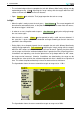
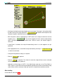
Table Of Contents
- Introduction
- User Interface
- Display Elements
- Cross Country Tasks
- Glide Computer
- Atmosphere and Instruments
- Airspace, Traffic and Team Flying
- Avionics and Airframe
- Quickstart
- InfoBox Reference
- Configuration
- Data Files
- About XCSoar
- GNU General Public License

8 AVIONICS AND AIRFRAME
8 Avionics and Airframe
This section discusses XCSoar as a subsystem of the aircraft. It covers the integration of XCSoar
with external devices, including GPS, switches and sensors, and aircraft radio transceivers and
other devices. Integration with FLARM is covered in section 7.9, and integration with variometers
is covered in section 6.1.
8.1 GPS connection
XCSoar requires a 3D GPS fix for its navigation functions.
GPS status
GPS status icons and text may appear on the bottom edge of the map display to indicate:
• Waiting for GPS fix The GPS may have a 2D fix, better reception or additional time to search
for satellites is required. The aircraft symbol disappears while there is no 3D fix.
• GPS not connected No communication with the GPS is received. This indicates an error in the
Comm port settings or the GPS device may be disconnected or switched off.
When the GPS is not connected for more than one minute, XCSoar automatically attempts to
restart communication with the device and will then resume waiting. This method has shown to
provide the most reliable way of recovering from communication errors.
XCSoar can handle up to two GPS sources and it uses them to provide redundancy. This means
that if the primary GPS source drops out, XCSoar will use the GPS data from the second source.
If both sources have valid fixes, the second source is ignored. For this reason, it is recommended
to have the GPS source with the best antenna or reliability as the primary device.
GPS altitude
Some older GPS units (and some new ones) do not output altitude relative to mean sea level, rather
they output elevation with respect to the WGS84 ellipsoid. XCSoar detects when this occurs and
applies the ellipsoid to geoid offset according to an internal tabulated data at two degree spacing.
This is not required for FLARM units or Altair Pro, which correctly output MSL altitude.
8.2 Switch inputs
XCSoar supports monitoring of switches and sensors connected to the host computer, for the
purpose of providing situational awareness feedback, alerts, or as general-purpose user-interface
input devices. Several mechanisms are available for interfacing to switches and sensors:
• Serial device Certain intelligent variometers such as triadis engineering’s Vega have multiple
airframe switches and pass this information to Altair/XCSoar as special NMEA sentences.
• OneWire device triadis engineering’s Altair glide computer and Vega variometer provide a OneWire
peripheral bus to which various digital and analog sensors can be attached.
A custom ‘input events’ file determines how switch and sensor inputs are processed.
A standard set of airframe inputs are defined as:
75 XCSoar Manual (Altair version) • XCSoar-A-EN