
User`s manual
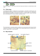
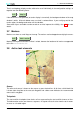
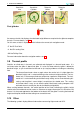

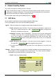
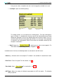
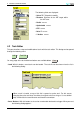
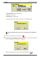
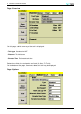
Table Of Contents
- Introduction
- User Interface
- Display Elements
- Cross Country Tasks
- Glide Computer
- Atmosphere and Instruments
- Airspace, Traffic and Team Flying
- Avionics and Airframe
- Quickstart
- InfoBox Reference
- Configuration
- Data Files
- About XCSoar
- GNU General Public License
3 DISPLAY ELEMENTS
CONF Setup Wind
The trail drift display is useful also to show more clearly when thermals are cranked due to wind
shear.
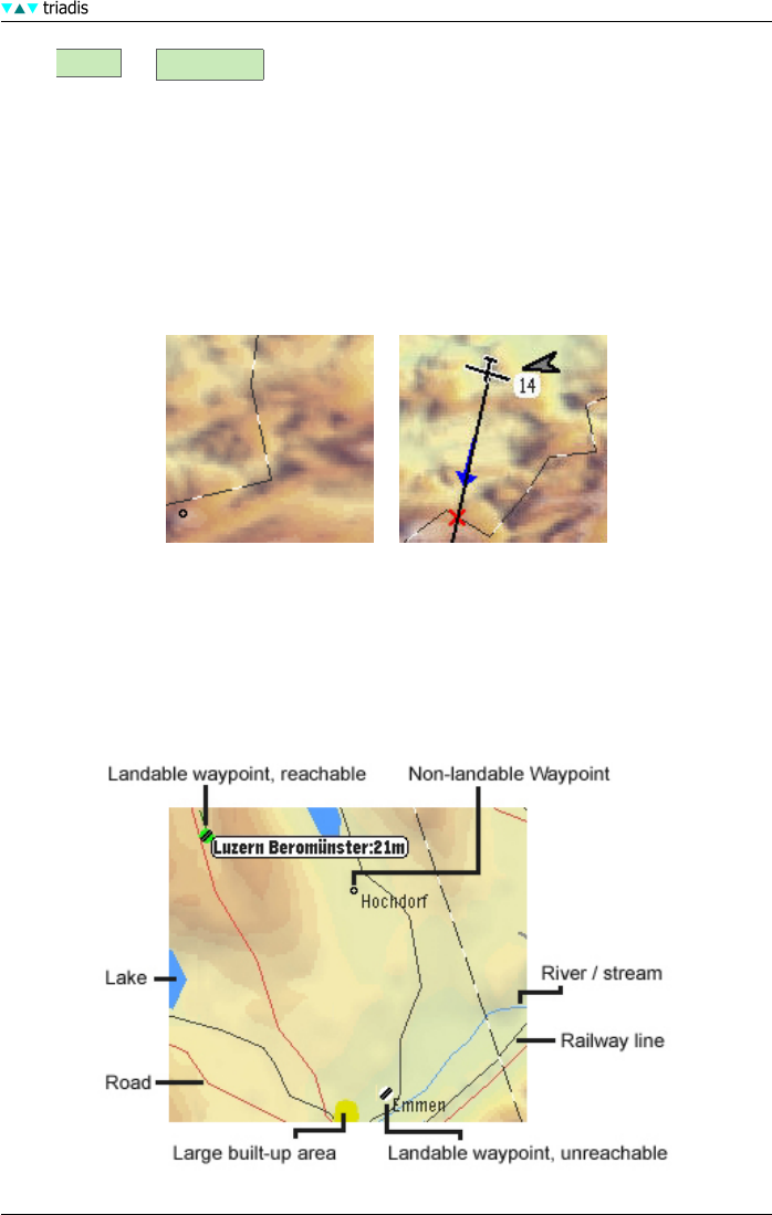
3.5 Glide range
A reachable glide ‘footprint’ is displayed on the map display as a dashed line, indicating where the
glider would descend through the terrain clearance height. This glide range line is calculated for
tracks extending in all directions. This feature is useful in assessing range with respect to topology
when searching low for lift, and when flying in mountainous areas.
The final glide path is checked for whether the glider clears terrain by the terrain clearance height.
If clearance is not attained, a red cross appears on the map at the point where the violation occurs.
No icon is drawn if there is no task defined.
3.6 Map elements
XCSoar Manual (Altair version) • XCSoar-A-EN 24