Manual (Altair version) Document name: Document version: Release date: XCSoar-A-EN 1.8 03/07/2008 triadis engineering GmbH – Eichholzstrasse 7 – Postfach – CH-3254 Messen Phone: +41 (0)31 768 15 15 – Fax: +41 (0)31 768 15 16 – Internet: www.triadis.ch – E-Mail: admin@triadis.
Notes i XCSoar Manual (Altair version) • XCSoar-A-EN
Preface Revision history Revision 1.6 EN 1.7 EN 1.7 GR 1.8 Date 15/09/2007 08/01/2008 02/02/2008 03/07/2008 Status released draft draft released Author J.Wharington D.Wettstein D.Wettstein D.Wettstein Changes, comments Standard XCSoar manual Altair version, layout rework German translation New features, XCSoar Altair version 5.2 This manual applies to XCSoar version 5.2. The authors reserve the right to update this manual as enhancements are made throughout the life of this product.
CONTENTS Contents 1 2 iii Introduction 1.1 Organisation of this manual . . . . . 1.2 System requirements . . . . . . . . 1.3 Running XCSoar . . . . . . . . . . . 1.4 Through-life support . . . . . . . . . 1.5 Using XCSoar safely . . . . . . . . . 1.6 Graphical elements in this document . . . . . . . . . . . . . . . . . . . . . . . . . . . . . . . . . . . . . . . . . . . . . . . . . . . . . . . . . . . . . . . . . . . . . . . . . . . . . . . . . . . . . . . . . . . . . . . . . . . . . .
CONTENTS 3 4 5 6 Display Elements 3.1 Zoom and map scale 3.2 Panning the map . . 3.3 Glider symbol . . . 3.4 Trail . . . . . . . . . 3.5 Glide range . . . . . 3.6 Map elements . . . 3.7 Markers . . . . . . 3.8 Active task elements 3.9 Thermal profile . . . 3.10 Other . . . . . . . . . . . . . . . . . . . . . . . . . . . . . . . . . . . . . . . . . . . . . . . . . . . . . . . . . . . . . . . . . . . . . . . . . . . . . . . . . . . . . . . . . . . . . . . . . . . . . . . . . . . . . . . . . .
CONTENTS 6.8 7 8 Analysis dialog: Wind, Temperature, Barograph and Climb history . . . . . . . 62 Airspace, Traffic and Team Flying 7.1 Airspace display . . . . . . . . . . 7.2 Incursion events . . . . . . . . . . 7.3 Airspace warning levels . . . . . . 7.4 Airspace warning dialog . . . . . . 7.5 Airspace warning acknowlegement 7.6 Airspace Info dialog . . . . . . . . 7.7 Airspace Browser dialog . . . . . . 7.8 Analysis dialog: Airspace . . . . . 7.9 FLARM traffic display . . . . . . . 7.
CONTENTS 11.3 11.4 11.5 11.6 11.7 11.8 11.9 11.10 11.11 11.12 . . . . . . . . . . . . . . . . . . . . . . . . . . . . . . . . . . . . . . . . . . . . . . . . . . . . . . . . . . . . . . . . . . . . . . . . . . . . . . . . . . . . . . . . . . . . . . . . . . . . . . . . . . . . . . . . . . . . . . . . . . . . . . . . . . . . . . . . . . . . . . . . . . . . . . . . . . . . . . . . . . . . . . . . . . . . . . . . . . . . . . . . . . . . . . . . . . . . . . . . . . . . . . . . . . . . . .
1 INTRODUCTION 1 Introduction This document is a pilot’s manual that describes the functionality of XCSoar when used with Altair. XCSoar is an open source glide navigation system for portable devices. The audience is assumed to have a sound knowledge of the fundamental theory of flight for gliders, and at least a basic working knowledge of cross-country soaring. Updates to the XCSoar software may result in some of this manual being out of date.
1 INTRODUCTION • Powering on Press and hold the PWR/ESC button for one second. The LED in the button will light up, and XCSoar will start after Altair has booted. • Powering off Press and hold the PWR/ESC button for approx. two seconds. Altair will switch off. • Escape Pressing the PWR/ESC button quickly acts as an Escape key, typically used to close dialog pages or as a cancel function.
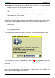
1 INTRODUCTION Last flight statistics The previous flight’s statistics are automatically saved when XCSoar is shut down, and loaded again at startup. This allows the flight to be reviewed even after shutting down Altair. Note that these persistent flight statistics use approximately 85 kilobytes of storage. Previous flight statistics are automatically reset on a new takeoff in order not to affect the current flight.
1 1.5 INTRODUCTION Using XCSoar safely The use of an interactive system like XCSoar in flight carries with it certain risks due to the potential distraction of the pilot from maintaining situational awareness and eyes outside the cockpit. The philosophy guiding the design and development of the software is to try to reduce this distraction by minimising the need for user interactions as much as possible, and by presenting information in a clear fashion able to be interpreted in a glance.
2 2 USER INTERFACE User Interface This section describes the fundamental user interface concepts used by XCSoar, and is intended as an overview. More detailed descriptions are given in following sections. The XCSoar display is composed of several parts: • Map area The bulk of the screen is dedicated to the GPS moving map display. Various symbols relating to glide computer information are overlaid on the map area.
2 USER INTERFACE • Dialog windows Larger dialog windows, usually containing graphics and buttons, are used to present detailed data to the pilot regarding waypoint details, statistics and analysis etc. To interact with XCSoar, you can either use the Altair buttons or external switches and devices connected to XCSoar. For XCSoarPC, clicking the mouse over an item is equivalent to touching it. 2.
2 USER INTERFACE If the user doesn’t interact with the computer for a certain time, the menu will close automatically. This menu timeout is configurable. The escape key on PC, or the PWR/ESC button on Altair, can also be used to close the current menu. Menu button labels appear as grey text instead of black if the corresponding function is not available. For example, the AAT Target button will appear grey if the task is not an AAT task.
2 USER INTERFACE • Team Code Opens Team Code . See 7.10 for more details. • AAT Target Configuration of the AAT target settings. See 4.1 for more details. 2.1.2 DISP menu • Pan On Activates pan map mode. See 3.2 for more details. • Mark Location Drops a marker at the current glider location. See 3.7 for more details. • Setup Display Opens Setup Display . See 2.3.6 for more details. • Map Off Switches terrain and topology on/off. • Default Restores default display settings.
2 USER INTERFACE 2.1.4 CONF menu • Setup MC Opens Setup MacCready . See 5.2 for more details. • Setup Basic Opens Basic Settings . See 5.4 for more details. • Setup Wind Opens Wind Settings . See 6.5 for more details. • Settings Airspace Opens Airspace Browser . See 7.7 for more details. • Setup Vega Opens Setup Vega if Vega is connected. See 6.1 for more details. • Setup System Opens the XCSoar configuration dialog. See 11 for more details. • Setup Logger Opens Altair Flight Recorder Setup . See 4.
2 USER INTERFACE • Analysis Show Opens Analysis . See the different ‘Analysis dialog: ...’ parts of this document for more details. • Checklist Opens Checklist . See 12.10 for more details. • Message Last Repeats the last status message.
2 USER INTERFACE 2.2 InfoBoxes The customizable InfoBoxes are used to display informations regarding atmosphere, flight, task, etc. The available fields are listed in section 11.12. Screen display modes The screen can be toggled between the following main display modes: • Map with standard InfoBoxes (flight mode specific; see 5.1 for more details). • Map with auxiliary InfoBoxes INFO . Aux Info On • Full-screen map, InfoBoxes hidden DISP .
2 USER INTERFACE In some dialogs, items that are not relevant or valid are not displayed (e.g. AAT details in a non-AAT task). We will now list all dialogs of the current XCSoar version like they appear in the onscreen menus. Most of them are described in detail in other sections; in these cases there is only a basic description in this part. 2.3.1 Waypoint Select Access: In navigation mode WayPoint: NAV . Change WayPoint Description: Search and change waypoints. For more details see 4.2. 2.3.
2 USER INTERFACE • Dsp Mode Change display mode. For more details see 2.2 resp. 5.1. • Airspace Airspace settings. For more details see 11.2. • Gliderange Switch gliderange on/off. For more details see 3.5. • Trail Change trail display settings. For more details see 3.4. • Terrain Switch terrain on/off. • Topology Switch topology on/off. • Labels Switch waypoint labels on/off. • Orientation Change map display orientation. For more details see 11.3. 2.3.7 Screen Brightness Access: DISP .
2 2.3.11 Access: USER INTERFACE Airspace Browser CONF . Settings Airspace Description: Search and modify display settings of airspaces. For more details see 7.7. 2.3.12 Access: Setup Vega CONF . Setup Vega Description: Vega settings. For more details see 6.1. 2.3.13 Access: Configuration CONF . Setup System Description: XCSoar configuration settings. For more details see 11. 2.3.14 Access: Altair Flight Recorder Setup CONF . Setup Logger Description: Altair Flight Recorder Setup.
2 USER INTERFACE 2.3.20 Checklist Access: INFO . Check list Description: Checklist can display several pages of user-defined free text, typically this is used for checklists. These checklists may include: daily inspection, preflight, outlanding, pre-landing, radio procedures, and aircraft rigging and de-rigging instructions. For more details see 12.10. 2.4 Status messages Status messages appear over the map area to present text for a short period of time.
2 USER INTERFACE Aircraft • Longitude Aircraft’s longitude • Latitude Aircraft’s latitude • Altitude Aircraft’s altitude • Max height gain xxxxxxx • Near Nearest waypoint • Bearing Bearing to nearest waypoint • Distance Distance to nearest waypoint System XCSoar Manual (Altair version) • XCSoar-A-EN 16
2 USER INTERFACE • GPS lock Whether a GPS source is connected. • Satellites in use Satellites used for GPS reception. • Vario Whether a variometer is connected. • FLARM Whether a FLARM device is connected. • Flight Recorder Type of flight recorder. • Declaration xxxxxxxx • Supply voltage Supply voltage. Task • Assigned task time Minimum AAT task time. • Estimated task time Estimated task time with current MacCready settings. • Remaining time Remaining time to final task point.
2 USER INTERFACE Rules • Valid start Whether a valid Start was recognized • Start time Start time • Start alt Start altitude • Start point Start task point • Start speed Start speed • Finish alt min Minimum finish altitude • Valid finish Whether a valid Finish was recognized Times XCSoar Manual (Altair version) • XCSoar-A-EN 18
2 USER INTERFACE • Local time Local time • Flight time Flight time • Takeoff time Takeoff time • Landing time Estimated landing time • Sunset Sunset at finish waypoint Flight Recorder • Type Flight Recorder Type • Identification Flight Recorder Identification • Version Flight Recorder Version • Time Flight Recorder Time • Last Declaration Time and date of last declaration 2.6 Text entry When needed, text can be entered over a virtual keyboard.
2 USER INTERFACE To enter text, rotate the knobs to choose a character with the cursor and press Enter. When the keyboard is open, the buttons on Altair have the following functions: ESC Esc 2.7 NAV Cap DISP Shift CONF áü INFO Enter F5 Back F6 Down F7 Up F8 Left F9 Right Sounds XCSoar generates sounds for different events, and can be configured to have custom sounds for any event. see 12.15 for details on customization.
3 DISPLAY ELEMENTS 3 Display Elements This section describes the different elements of the display. 3.1 Zoom and map scale The map is generated in a projected coordinate system (not longitude and latitude). The map scale may be modified (zooming) at any time and the map can be panned. All navigation functions take account of the earth curve. To zoom in and out in manual zoom mode, use the rotary knob. The map scale is displayed in the lower left corner of the moving map display.
3 DISPLAY ELEMENTS 3. When done, pan mode should be disabled, by activating the menu again: DISP . Pan Off or by pressing ESC. When pan is active, the text ’PAN’ appears next to the map scale and a special row of buttons is displayed (see 2.1.3). The location of focus moves and rotates with the glider when panning. 3.3 Glider symbol The glider symbol shows the position of the glider on the map. The orientation of the glider indicates the estimated heading of the glider.
3 DISPLAY ELEMENTS 3.4 Trail An optional trail is drawn on the map showing the glider’s path history. The colour and thickness of the trail depends on the variometer value; with lift areas being presented in green and thicker lines, sink areas being presented in red with thin lines. Zero lift is presented as a grey line.
3 CONF . DISPLAY ELEMENTS Setup Wind The trail drift display is useful also to show more clearly when thermals are cranked due to wind shear. 3.5 Glide range A reachable glide ‘footprint’ is displayed on the map display as a dashed line, indicating where the glider would descend through the terrain clearance height. This glide range line is calculated for tracks extending in all directions.
3 DISPLAY ELEMENTS The moving map shows: • Waypoints • Terrain and topology • Markers The map is drawn in a projected coordinate system (not latitude and longitude), and the scale can be changed (zooming in and out), as well as panned. All navigation functions take the curvature of the Earth into account. Waypoints Waypoints are displayed with different symbols depending on the waypoint type; the major distinction being landable and non-landable waypoints.
3 DISPLAY ELEMENTS Terrain and topology display can be switched on or off individually in the configuration settings, or together over the following menu: DISP . Map Off If the terrain file is not specified (or terrain display is turned off), the background colour of the map window is white. All terrain below mean sea level is coloured blue. If you are flying outside the terrain region, the background colour will also be blue.
3 DISPLAY ELEMENTS Start/finish Line Start/finish Cylinder Taskpoint Sector Taskpoint AAT Final glide bar An arrow on the left side displays the calculated height difference required for the glider to complete the task. For more details, see 5.8. On this arrow, a letter is displayed, which indicates the current task navigation mode: • T NavTo Task Point • L NavTo Landing Point • W NavTo Way Point For more information about the navigation modes see 4.1. 3.
3 DISPLAY ELEMENTS GPS not connected GPS waiting for fix Cruise Climb Final glide XCSoar Manual (Altair version) • XCSoar-A-EN 28
4 CROSS COUNTRY TASKS 4 Cross Country Tasks This section describes the handling of tasks in XCSoar. Please note that there is always an active task in XCSoar, which contains at least a start and a landing point (standard: homebase). This active task and its modifications are automatically saved and restored when you switch the device off and on. For more details about setting up and modifying tasks, see 4.2. 4.1 NAV Menu You can modify a task before and during flight through the NAV menu.
4 CROSS COUNTRY TASKS Here you can chose a taskpoint from the list of the waypoints available in the task. • .. LandingPt Opens the following dialog: This dialog contains a list of maximum ten landing points. For each landing point, type (A: Airfield, L: Landable field), distance, course and altitude difference to safety altitude are displayed as well as the required glide rate to reach this point. The list is sorted by glide rate and landing point type (airfields are at the top).
4 CROSS COUNTRY TASKS The following fields are displayed: • Select TP Taskpoint to modify. • Distance Distance of the AAT target within the AAT area. • Radial xxxxxx • Optimizable xxxxxx • ETE xxxxxx • Delta T xxxxxx • V Achiev xxxxxx 4.2 Task Editor This part describes setup and modification of tasks with the task editor. This dialog can be opened through the following menu: NAV .
4 CROSS COUNTRY TASKS • Save and Download Save and declare task. • Save only Only save task. • Download only Only declare task. If you want to declare a task, you have to confirm this in the following dialog: A task may be modified at any time, but it can only be declared to a logger before flight. • Calc Opens the task calculator. For more details, see 4.3. • New Cleans out the current waypoint list and sets the homebase as start and finish waypoint.
4 CROSS COUNTRY TASKS Page: Overview On this page, a brief summary of the task is displayed: • Task type Standard or AAT • Distance Task distance • Enroute Time Estimated task time Below these fields, the task points are listed (S: Start, F: Finish). On the bottom of the page, comments about this task may be displayed.
4 CROSS COUNTRY TASKS On this page, you can set the task options: • Name Task file name. • Type Standard or AAT • Advance Type of advance to the next taskpoint when flying through a taskpoint area: • Manual Manual advance throuth NAV . Advance (manual) . • Auto Automatic advance when the glider flies through the taskpoint area (or, for start, finish or AAT taskpoints, when the specific requirements are met). The next taskpoint is automatically chosen from the task point list.
4 CROSS COUNTRY TASKS Page: Waypoints On this page, all task points are listed. The following buttons are available: • Insert With this button, new task points can be added through the following dialog: In this dialog you can search and select waypoints. Filters (name, distance, direction, type) on the left side make this search easier. Distance and direction are always relative to the aircraft.
4 CROSS COUNTRY TASKS • Landable Sets the field ‘Type’ to ‘Landable’. All landable waypoints are displayed. • Airport Sets the field ‘Type’ to ‘Airport’. All airports are displayed. • Home xxxxxxxx These filters may be used in combination. • Remove Removes the selected waypoint from the list. A task always has at least a start and a finish task point (standard: homebase). These can not be deleted. • Up Moves the selected task point up (earlier in the task).
4 CROSS COUNTRY TASKS Page: Rules On this page you can set the rules for the current task: • Start max Speed Maximum allowed velocity in start area. 0 = no maximum velocity. • Start max Height Maximum allowed height over ground at task start. 0 = no maximum height. • Finish min Height Minimum height over ground at task finish. 0 = no minimum height. • FAI Finish Height FAI Finish height (1000m rule). • Online Contest Rules for OLC path optimization: • Sprint Conforms to FAI IGC League rules.
4 CROSS COUNTRY TASKS Page: IGC Settings On this page you can specify the IGC specific task parameters used for declaration. 4.3 Task calculator The task calculator is essetially used for AATs. It shows informations about the current task: • Assigned task time (Only AAT) Minimum AAT task time. • Estimated task time Estimated task time at current MacCready. • Task distance Remaining distance to finish task point.
4 CROSS COUNTRY TASKS • Set range (Only AAT) Allows modification of turning point positions inside the remaining AAT areas (-100% to +100%) and shows the influence of these modifications on estimated task time and distance. • Speed remaining Estimated speed for the remaining part of the task at current MacCready. • Achieved MacCready Achieved MacCready value. • Achieved Speed Achieved average speed. These buttons are available: • Close MC Closes the task calculator and saves the MacCready modification.
4 CROSS COUNTRY TASKS • Near Sets the field ‘Distanz’ to 25km. When pressed again, the value changes to 50, 75 and 100km. All waypoints within this distance are displayed in the list. • Ahead Sets the field ‘Direction’ to HDG(360◦ ). All waypoints within a certain angle (30◦ ) on both sides of the aircrafts heading direction are displayed. • Landable Sets the field ‘Type’ to ‘Landable’. All landable waypoints are displayed. • Airport Sets the field ‘Type’ to ‘Airport’. All airports are displayed.
4 CROSS COUNTRY TASKS 4.6 AAT AAT Targets A target is a point within an AAT area that the pilot intends to fly to. These targets can be moved within the AAT areas so the pilot can adjust the effective distance of the task. Targets may be set on the ground, during task planning, and modified during flight.
4 CROSS COUNTRY TASKS • While the aircraft is in the AAT sector and the distance from the previous target to the aircraft is greater than the distance from the previous target to the current target, the target is moved further along the projected line from the previous target to the aircraft, just beyond the aircraft. Hence, the black track line will not be visible but the blue optimal track arrow will point along this projected direction. 4.
4 CROSS COUNTRY TASKS In the OLC analysis page, the aircraft track is shown as a thin green line, and after optimisation, the optimal path is shown as a thick red dashed line. If continued flight in final glide will result in higher score, the displayed results are shown as ‘In progress’ and a blue line shows the projected path to improve the score. For Sprint and Classic OLC types, this path is extended in the direction to the current waypoint.
4 CONF .
5 GLIDE COMPUTER 5 Glide Computer This section focuses on how XCSoar’s glide computer works and is recommended reading so you understand the specific details of calculations being performed and how to use the software properly. It assumes a basic knowledge of cross-country soaring, but is suitable reading for competition pilots as well as pilots engaging in casual cross-country touring. 5.1 Flight modes XCSoar automatically detects the difference between thermal (circling) flight and cruising flight.
5 • DISP . GLIDE COMPUTER Setup Display • F7 For informations about individual customization of the InfoBoxes see 11.12. 5.2 MacCready settings When connected to a supported intelligent variometer, adjusting the MacCready setting on the variometer will change the setting in XCSoar. If no variometer is connected, the MacCready value can be adjusted through the following menu: CONF .
5 GLIDE COMPUTER Similarly, when below final glide altitude, the MacCready ring setting my be decreased, resulting in a lower speed to be commanded. Because the ring setting has decreased, the pilot may be prepared to stop and circle in weaker thermals. Auto MacCready performs this adjustment automatically and continuously.
5 GLIDE COMPUTER The build-up of bugs on the wing’s leading edge, as well as rain droplets on the wing, affect the aerodynamic performance. It is the pilot’s responsibility to judge and update the bugs value during flight. The bugs value is expressed as a percentage of the clean glider’s performance. For example, at 100% bugs value, the glider performs as a clean glider, and at 50% bugs value, the glider’s sink rate is doubled when compared to a clean glider.
5 GLIDE COMPUTER The QNH is only updated if the aircraft is on the ground for more than 10 seconds, so that if XCSoar is restarted during flight, QNH will not be adjusted. The update only occurs also if the terrain database is valid at the current aircraft location. • Max Temp The maximum forecast ground temperature is used by the convection forecast algorithm (see 6.7) in its determination of estimated convection height and cloud base. 5.
5 GLIDE COMPUTER Speed to fly with risk The speed to fly system can be compensated for risk, in which the MacCready setting used for calculating the speed to fly (in both Block or Dolphin modes) is reduced as the glider gets low. This feature performs automatically what many pilots use to do manually. The theory governing how this is implemented in XCSoar is based loosely on the paper by John Cochrane, “MacCready Theory with Uncertain Lift and Limited Altitude” Technical Soaring 23 (3) (July 1999) 88-96.
5 GLIDE COMPUTER The safety heights are: • Arrival height This is the elevation above ground at which the glider is required to arrive at for a safe landing circuit, plus some safety margin. This value is used in final glide calculations as well as the determination and display of reachable landable fields. • Terrain clearance This is the elevation above ground, below which any computed glide path is considered to provide inadequate clearance to the terrain.
5 GLIDE COMPUTER When calculating the arrival heights of landable fields (for map display purposes and in abort mode), a safety MacCready value can be specified in the configuration settings. This safety value is set to zero by default. Larger values make the arrival height calculation more conservative. All these safety heights can be defined in the configuration settings on the page ‘Safety factors’. 5.
5 GLIDE COMPUTER 5.8 Display of altitude required On the left side of the map display, a box displays the calculated height difference required for the glider to complete the task, or reach the final waypoint. If the glider is above the minimum height required, a green arrow bar is drawn above the box indicating the amount of excess height. If the glider is below the minimum height required, a red arrow bar is drawn below the box indicating the amount of height deficit.
5 GLIDE COMPUTER In this situation, if the glider is climbing, the pilot can assess whether to leave the thermal early and commence a final glide descent at a reduced MacCready setting; or continue to climb. It is useful to switch on the auto MacCready setting as this will automatically adjust the MacCready value to the optimal value – and then it is simple for the pilot to compare the achieved lift rate with the MacCready value.
5 GLIDE COMPUTER • Task speed instantaneous This is the instantaneous estimated speed along the task. When climbing at the MacCready setting, this number will be similar to the estimated task speed. When climbing slowly or flying off-course, this number will be lower than the estimated task speed. In cruise at the optimum speed in zero lift, this number will be similar to the estimated task speed. This measure, available as an InfoBox is useful as a continuous indicator of the cross-country performance.
5 GLIDE COMPUTER it will arrive at the waypoint in minimum time. When the wind is negligible, or when the computer is in final glide mode, this arrow will point along the black line that indicates the track to the next waypoint. The calculation and display of optimal cruise track is a unique feature of XCSoar. Commonly, when cruising between thermals, glide navigation systems direct the glider to steer so that the glider’s track points directly at the target.
5 GLIDE COMPUTER glide polar, this enables investigation of whether the glider is being flown optimally with respect to flap settings and also to investigate the benefits of performance optimisation such as sealing control surfaces etc. Data is collected only when in cruise mode and at G loading between 0.9 and 1.1; so pilots performing test flights should attempt to fly smoothly with wings level. 5.
6 6 ATMOSPHERE AND INSTRUMENTS Atmosphere and Instruments XCSoar maintains an internal model of the atmosphere based on statistics gathered from the flight path and other instruments connected to the device. These statistics and measurements are approximate and the weather can on some days change rapidly. The pilot should at all times keep observing the weather. In particular, when out-landing in fields, the pilot should look for indicators on the ground to confirm wind strength and direction. 6.
6 ATMOSPHERE AND INSTRUMENTS 6.2 Air data inputs Where additional aircraft dynamics or air mass data are provided by an intelligent variometer, XCSoar can often make use of it or display it in a separate InfoBox. Key sensor measurements that XCSoar uses include: • Gross total energy variometer (rate of change of the total energy of the aircraft) Used for display, and for calculation of netto variometer.
6 ATMOSPHERE AND INSTRUMENTS One of the following estimation methods can be set either in the configuration settings (page ‘Glide Computer’, field ‘Auto Wind’) or in Wind Settings : • Manual • Circling • ZigZag • Both (ZigZag and Circling) When wind estimates change significantly, a status message notification of this is issued. Circling wind algorithm XCSoar estimates the wind magnitude and direction when circling.
6 ATMOSPHERE AND INSTRUMENTS The wind value can be saved so that the estimate is restored next time XCSoar starts. At any time during flight, the pilot can make corrections to the wind estimate by entering the correction in the wind settings dialog and pressing the Save Wind button. Once Save Wind is pressed, the internal estimate is ignored until a new internal estimate is obtained from the circling or zigzag algorithm.
6 6.7 ATMOSPHERE AND INSTRUMENTS Convection forecast If the glider is equipped with an outside temperature and humidity probe, a simple convection forecast system estimates the convection ceiling and the cloud base. The humidity probe is optional and is mainly required for estimating cloud base. Prior to takeoff or during flight the pilot can modify the maximum forecast temperature on the ground by adjusting the value in Basic Settings described in subsection 5.4.
6 ATMOSPHERE AND INSTRUMENTS • Temp trace This page is only available if a supported instrument is connected to XCSoar that produces outside air temperature and humidity. The chart shows the variation of dry air temperature, dew point temperature and outside air temperature with height. The convection forecast is summarised as the estimated thermal convection height and estimated cloud base. Settings opens Basic Settings . • Barograph Shows a graph of the history of the altitude of the glider.
6 XCSoar Manual (Altair version) • XCSoar-A-EN ATMOSPHERE AND INSTRUMENTS 64
7 AIRSPACE, TRAFFIC AND TEAM FLYING 7 Airspace, Traffic and Team Flying A database of Special Use Airspace (SUA) can be loaded into XCSoar and used for both display of the airspace regions as well as detecting when the glider enters and leaves the regions. Two airspace files can be set in the configuration settings (page ‘Site’). The first of these is intended for use as the primary SUA database, the second is intended for use with short-term or changing airspace such as the airspace defined in NOTAMs.
7 AIRSPACE, TRAFFIC AND TEAM FLYING The default colouring of Class C, D, E and F airspace is consistent with ICAO charts. 7.2 Incursion events Three types of events are detected by XCSoar in relation to SUA: • Predicted incursion This event is detected when the glider is estimated to be on a track that will result in entering the airspace at a set time in the future. The time is the ’airspace warning time’ configuration setting.
7 AIRSPACE, TRAFFIC AND TEAM FLYING 7.4 Airspace warning dialog This dialog shows the most recent airspace warnings. The following details are shown: ... ... The glider’s position in relation to the airspace is shown with symbols: The glider is inside the airspace. The glider is horizontally beside the airspace. The glider is below the airspace.
7 7.5 AIRSPACE, TRAFFIC AND TEAM FLYING Airspace warning acknowlegement When Airspace Warnings is visible and an airspace warning is active, the dialog can be closed by pressing Close resp. ESC. This has the effect of closing the warning without actually acknowledging the warning.
7 AIRSPACE, TRAFFIC AND TEAM FLYING The airspaces can be filtered by Name, Distance, Heading and Type (class or status). Four buttons have specific filter functions: • Near Sets the distance on 25km. Pressing the button another time sets it on 50, 75 and 100km. All airspaces within this distance are shown. • Ahead Sets the field ‘Direction’ to HDG(360◦ ). All airspaces within a certain angle (30◦ ) on both sides of the aircrafts heading direction are displayed. • Disabled Sets the type to ‘Disabled’.
7 AIRSPACE, TRAFFIC AND TEAM FLYING To search airspaces, you can use the same filtering methods as in Airspace INFO (see previous subsection). Modify settings To modify warning and display settings of a single airspace, select the airspace from the list and press Enter. The following dialog shows up: You can now modify the settings (warnings, visibility) for the selected airspace. To modify the settings for a whole class, press Classes (F9).
7 AIRSPACE, TRAFFIC AND TEAM FLYING Choose a class and press Enter. You can now modify the warnings and visibility settings. Changes of airspace display colors can be done on the ‘Airspace’ page of the configuration settings. See 11.2 for more details. 7.8 Analysis dialog: Airspace The analysis dialog contains a page showing a cross-section of the airspace. This is accessed via the menu under INFO .
7 AIRSPACE, TRAFFIC AND TEAM FLYING Browse opens Airspace Browser . 7.9 FLARM traffic display If connected to a FLARM device, FLARM traffic is displayed on the map area. Each FLARM aircraft received is drawn as a dashed red disk. Do not use XCSoar for collision avoidance, as FLARM audio devices are much more suitable in assisting the pilot to be aware of traffic. Note that unless one is circling, the usual zoom level is such that FLARM traffic will not be easily distinguished.
7 AIRSPACE, TRAFFIC AND TEAM FLYING The FLARM gauge display shows FLARM traffic in colours according to the threat level: • Green for level 0 • Yellow for level 1 • Red for level 2 and 3 The style of the FLARM radar can be customised with the ‘FLARM symbols’ configuration option on page ‘Appearance’ of the configuration settings. This controls the symbols used to display FLARM targets on the radar display.
7 7.10 AIRSPACE, TRAFFIC AND TEAM FLYING Team flying Team code is a system to allow pilots flying within a team to communicate their position to each other in a concise and accurate manner. The principle of the system is that each pilot uses their computer to determine a 5 digit code which describes their position relative to a common waypoint. The pilots call each other reporting these codes, and entering the codes into the computer allows their mates to be located accurately by the computer.
8 AVIONICS AND AIRFRAME 8 Avionics and Airframe This section discusses XCSoar as a subsystem of the aircraft. It covers the integration of XCSoar with external devices, including GPS, switches and sensors, and aircraft radio transceivers and other devices. Integration with FLARM is covered in section 7.9, and integration with variometers is covered in section 6.1. 8.1 GPS connection XCSoar requires a 3D GPS fix for its navigation functions.
8 AVIONICS AND AIRFRAME • Airbrake • Flap position (positive, neutral, negative) • Landing gear Other logical inputs from Vega include computed quantities relating to specific airframe alerts and aircraft operating envelope warnings, for example “airbrake extended and gear retracted”. Refer to the Vega documentation for more details on switch inputs and how they may be used. 8.3 Switch Status When a Vega is connected, the switch status is shown on the last page of available from the menu: CONF .
8 AVIONICS AND AIRFRAME 8.6 Other avionics devices Support for the Honeywell Digital Compass HMR3000 is under development. 8.7 Slave mode A device type in the configuration settings, “NMEA Out” is defined for use in joining two Altair systems in a master-slave mode. In the master, the second COM device can be set to NMEA Out, and all data received in the first com device (as well as outgoing data) will be sent to the slave.
9 9 QUICKSTART Quickstart This section provides instructions for using XCSoar in typical cross-country tasks. It is separated into simple scenarios to demonstrate how to use key features. It assumes the configuration options have already been set up to the user’s preferences. These instructions are intended to provide a simple step-by-step guide to flying tasks of varying levels of complexity but are not intended to demonstrate all the features of XCSoar.
9 QUICKSTART 9.2 FAI Task In this scenario, the pilot intends to fly a triangle FAI task with a single start sector and automatic waypoint advance. Prior to takeoff • Turn on the device. • Open Basic settings and adjust the bugs and ballast as required. Set the maximum forecast temperature. Close the dialog. • Open Task editor and press New . • The task now contains the home waypoint as start and finish waypoint. • Add new waypoints with Insert on the ‘Waypoints’ page.
9 QUICKSTART After landing As described in subsection 9.1. 9.3 FAI Task, Manual Start In this scenario, the pilot intends to fly a triangle FAI task with a single start sector and manual task start. Prior to takeoff As described in subsection 9.2, except where noted below. • Set ‘Auto Advance’ to ‘Arm start’ in Task editor . In-flight As described in subsection 9.2, except where noted below. • Prior to entering the start sector, when you are ready to start the task, press the ‘NavTo TaskPt’ button.
9 QUICKSTART • The estimated elapsed time to complete the task with different MacCready settings can be explored by pressing Calc . Adjusting the ’range’ setting shifts the targets within the AAT sectors to increase or decrease the task distance. • Open Analysis and select the ‘Task’ page to preview the task on a map. In-flight • When the pilot is ready to start the task, press Arm Advance . The current waypoint will then advance automatically once, as the pilot flies through the start sector.
9 QUICKSTART • At all times the black track arrow will point at the next target. The target is the location within the AAT sector at the range specified in Task calculator . The blue arrow will point at the direction the glider should track when in cruise. • When the pilot is within or approaching an AAT sector and is ready to advance to the next waypoint, press Arm Advance . The current waypoint will then advance automatically once, if the pilot is inside the observation zone.
9 QUICKSTART 9.5 Task with alternate start sectors In this scenario, the pilot intends to fly a task with alternate start sectors and manually arm the waypoint advance system. Prior to takeoff As described in subsection 9.2, except where noted below. • Open Task editor , and set ‘Auto Advance’ to ‘Arm start’. Set ‘Alternate Start Points’ to ‘ON’ on the ‘Options’ page. Press Enter on the start waypoint in ‘Waypoints’ and then press Altern. Starts .
10 10 INFOBOX REFERENCE InfoBox Reference InfoBox data types are grouped into logical categories. All InfoBoxes display their data in user-specified units. Where data is invalid, the displayed value will be ’–’ and the contents are greyed out. This happens, for example, when no terrain data is found or it is not in range for the Terrain Elevation InfoBox type.
10 INFOBOX REFERENCE Track Magnetic track reported by the GPS. Airspeed IAS Indicated Airspeed reported by a supported external intelligent vario. G load Magnitude of G loading reported by a supported external intelligent vario. This value is negative for pitch-down manoeuvres. Bearing Difference The difference between the glider’s track bearing, to the bearing of the next waypoint, or for AAT tasks, to the bearing to the target within the AAT sector.
10 INFOBOX REFERENCE Next L/D The required glide ratio to reach the next waypoint, given by the distance to next waypoint divided by the height required to arrive at the safety arrival altitude. Negative values indicate a climb is necessary to reach the waypoint. If the height required is close to zero, the displayed value is ’–’. L/D vario Instantaneous glide ratio, given by the indicated airspeed divided by the total energy vertical speed, when connected to an intelligent variometer.
10 INFOBOX REFERENCE Vario Instantaneous vertical speed, as reported by the GPS, or the intelligent vario total energy vario value if connected to one. Netto Vario Instantaneous vertical speed of air-mass, equal to vario value less the glider’s estimated sink rate. Best used if airspeed, accelerometers and vario are connected, otherwise calculations are based on GPS measurements and wind estimates. 10.5 Atmosphere Wind Speed Wind speed estimated by XCSoar. Wind Bearing Wind bearing estimated by XCSoar.
10 INFOBOX REFERENCE Speed MacCready The MacCready speed-to-fly for optimal flight to the next waypoint. In cruise flight mode, this speed-to-fly is calculated for maintaining altitude. In final glide mode, this speed-to-fly is calculated for descent. Percentage climb Percentage of time spent in climb mode. These statistics are reset upon starting the task.
10 INFOBOX REFERENCE Speed Task Average Average cross country speed while on current task, compensated for altitude. Speed Task Instantaneous Instantaneous cross country speed while on current task, compensated for altitude. Speed Task Achieved Achieved cross country speed while on current task, compensated for altitude. Final Distance Distance to finish around remaining turn points. AA Time Assigned Area Task time remaining.
10 INFOBOX REFERENCE AA Distance Tgt Assigned Area Task distance around target points for remainder of task. AA Speed Tgt Assigned Area Task average speed achievable around target points remaining in minimum AAT time. Distance Home Distance to the home waypoint (if defined). 10.8 Waypoint Next Waypoint The name of the currently selected turn point. When this InfoBox is active, using the up/down cursor keys selects the next/previous waypoint in the task.
10 INFOBOX REFERENCE Next Time To Go Estimated time required to reach next waypoint, assuming performance of ideal MacCready cruise/climb cycle. Task Arrival Time Estimated arrival local time at task completion, assuming performance of ideal MacCready cruise/climb cycle. Next Arrival Time Estimated arrival local time at next waypoint, assuming performance of ideal MacCready cruise/climb cycle. 10.9 Team code Own Team Code The current Team code for this aircraft.
11 11 CONFIGURATION Configuration XCSoar is a highly configurable glide computer and can be customised to suit a wide variety of preferences and user requirements. This section describes the configuration settings and options. Scope of configuration Several features of XCSoar can be customised: • Modifying configuration settings. This is the sort of configuration most likely to be performed by users; and this is given the greatest attention in this document.
11 CONFIGURATION Fail-safe If the XCSoar software crashes due to an unrecoverable error while loading a file, the file will be removed from the configuration settings in order to prevent the crash reoccuring. Therefore, if an error was found in a file, the user must re-enter that file in the configuration settings after remedying the situation.
11 11.1 CONFIGURATION Site The dialog specifies most of the important files that must be configured when flying at a new site. • Map file The name of the map file (XCM) containing digital elevation terrain data, topology, waypoints etc. • Waypoints 1 Primary waypoints file. If left blank, waypoints are loaded from the map file (if available).
11 CONFIGURATION 11.2 Airspace This page is used to determine how the airspace information is displayed and how warnings are issued. • Airspace display Controls how airspace display and warnings are filtered based on altitude. Filtering options for single airspaces or airspace classes are available in (see 7.7 for more details). Airspace Browser • All off No airspaces are shown on the map. • All on All the airspace information is displayed at the same time.
11 CONFIGURATION This page also has Colours which can be used to review or change the colours/patterns used by each airspace class. When pressed, the following dialog is opened: First select the airspace type you wish to change. Then press Enter and select the colour and pattern you wish it to be drawn in.
11 CONFIGURATION 11.3 Map Display This page has options relating to the map display. • Labels This setting determines the label displayed with each waypoint. There are 6 options: • Names The full name of each waypoint is displayed. • Numbers The waypoint number of each waypoint is displayed. • None No names are displayed with the waypoints. • Names in task Names are only displayed for waypoints that are in the active task as well as the home airfield.
11 CONFIGURATION • Target up when circling This is equivalent to track-up in cruise and the bearing to next waypoint up when circling. • North/track North-up in cruise, glider track-track up in circling • Auto zoom Determines whether auto-zoom is enabled. Auto-zoom changes the zoom level during flight so that the map zooms in as the active waypoint is approached. After passing a waypoint, the map zooms out to the next waypoint.
11 CONFIGURATION 11.4 Terrain display This page sets how terrain and topology is drawn on the map window. • Terrain display Draws digital elevation terrain on the map • Topology display Draws topological features (roads, rivers, lakes) on the map • Terrain contrast Defines the amount of phong shading in the terrain rendering. Use large values to emphasise terrain slope, smaller values if flying in steep mountains. • Terrain brightness Defines the brightness (whiteness) of the terrain rendering.
11 CONFIGURATION Colour schemes XCSoar Manual (Altair version) • XCSoar-A-EN 100
11 CONFIGURATION 11.5 Glide computer This page allows glide computer algorithms to be configured. • Glide terrain line This determines whether the glide terrain range is calculated and drawn as a line on the map area. • Auto wind This allows switching on or off the automatic wind algorithm. When the algorithm is switched off, the pilot is responsible for setting the wind estimate. Circling mode requires only a GPS source, ZigZag requires an intelligent vario with airspeed output.
11 CONFIGURATION • NAV by baro altitude When enabled and if connected to a barometric altimeter, barometric altitude is used for all navigation functions. Otherwise GPS altitude is used. • Flap forces cruise When this option is enabled, causes the flap switches in Vega to force cruise mode when the flap is not positive. This means that when departing a thermal, switching to neutral or negative flap will immediately switch XCSoar’s mode to cruise mode.
11 CONFIGURATION 11.6 Safety factors This page allows the safety heights and behaviour in abort mode to be defined. • Arrival height The height above terrain that the glider should arrive at for a safe landing. • Breakoff height This is the height above terrain, below which the pilot should abort the task and prepare for an outlanding. • Terrain height The height above terrain that the glider must clear during final glide.
11 11.7 CONFIGURATION Polar This page allows the glide polar to be defined. • Type This contains a selection of gliders of different performance classes, as well as a special entry for ‘WinPilot File’. • Polar file When ‘WinPilot File’ is the polar type, this is the name of the file containing the glide polar data. • V rough air The maximum manoeuvring speed can be entered on this page to prevent the glide computer from commanding unrealistic cruise speeds.
11 CONFIGURATION 11.8 Devices The Devices page is used to specify the ports used to communicate with the GPS and other serial devices. The default settings are COM1 and 4800 bits per second. When connected to the Vega intelligent variometer, the settings should be COM1 and 38400. Two COM devices are available (device A and device B), to allow, for example, one to be connected to a GPS and another to be connected to a second device such as a variometer.
11 11.9 CONFIGURATION Units This page allows you to set the units preferences used in all displays, InfoBoxes, dialogs and input fields. Separate selections are available for speed, distance, lift rate, altitude, task speed and latitude/longitude. The ‘UTC offset’ field allows the UTC local time offset to be specified. The local time is displayed below in order to make it easier to verify the correct offset has been entered. Offsets to the half-hour may be set.
11 CONFIGURATION 11.10 Interface This page defines some general display features of XCSoar. • Safety lock This determines whether the configuration settings dialog is accessible during flight. • Msg window Defines the alignment of the status message box, either centered or in the top left corner. • Events The Input Events file defines the menu system and how XCSoar responds to button presses and events from external devices.
11 11.11 CONFIGURATION Appearance This page defines various display styles used by symbols and InfoBoxes. • Glider position Defines the location of the glider drawn on the screen in percent from the bottom. • Final glide bar Two styles are available: Default and Alternate. The differences between these styles is cosmetic. Alternate displays the height difference to the right of the final glide bar; default displays the height difference above/below the final glide bar and inside a rounded box.
11 CONFIGURATION • ON/Scaled FLARM radar enabled, map display enabled and auto scaled. When auto scaling is enabled, the FLARM targets on the map display are scaled so that when the map is at large zoom levels, targets are still visible. • FLARM symbols This controls the symbols used to display FLARM targets on the radar display. • Relative altitude The relative altitude of the target is represented as a shape that becomes triangular for extreme above/below heights, square at the same altitude.
11 11.12 CONFIGURATION InfoBox This page allows the configuration of InfoBoxes to be defined in each InfoBox display mode (circling, cruise, final glide and auxiliary). See 2.2 for a description of the InfoBox types and their meanings. Click on the InfoBox to set the different display modes. Vario Gauge By clicking on the Vario gauge, you can configure the following options: • Speed arrows Whether to show speed command arrows on the Vario gauge.
12 DATA FILES 12 Data Files Data files used by XCSoar fall into two categories: • Flight data files These files contain data relating to the aircraft type, airspace and maps, waypoints etc. • Program data files These files contain data relating to the ‘look and feel’ of the program, including language translations, button assignments, input events, dialog layouts. This section focuses on flight data files; see the XCSoar Advanced Configuration Guide for details on program data files. 12.
12 DATA FILES Several commercial and freely distributable programs exist for converting between different waypoint formats. If the elevation of any waypoints is set to zero in the waypoint file, then XCSoar estimates the waypoint elevation from the terrain database if available. Furthermore, if the terrain database is available, then waypoints outside the terrain coverage area cause a dialog to open asking the user if these waypoints are individually or all to be ignored (excluded) or loaded (included).
12 DATA FILES 08 (RL1,7) 17 (RL53) 26 (R) 35 (R) COMMUNICATIONS: CTAF - 122.5 REMARKS: Nstd 10 NM rad to 5000’ REMARKS: CAUTION - Animal haz. Rwy 08L-26R and 17L-35R for glider ops and tailskidacft only, SR-SS. TFC PAT - Rgt circuits Rwy 08R-26L. NS ABTMT - Rwy 17R-35L fly wide ICAO: YBLA [GROOTE EYLANDT] ... 12.8 Glide polar The WinPilot format is used for glide polar files (extension .plr). The WinPilot and XCSoar websites provide several glide polar files.
12 DATA FILES *LS-3 WinPilot POLAR file: MassDryGross[kg], *MaxWaterBallast[liters], Speed1[km/h], Sink1[m/s], *Speed2, Sink2, Speed3, Sink3 373,121,74.1,-0.65,102.0,-0.67,167.0,-1.85 Don’t be too optimistic when entering your polar data. It is all too easy to set your LD too high and you will rapidly see yourself undershooting on final glide.
115 1-26E 1-34 1-35A 1-36 Sprite 604 ASH-25M 2 ASH-25M 1 ASH-25 (25m, PAS) ASH-25 (25m, PIL) ASH-26E ASG29-18 AstirCS ASW-12 ASW-15 ASW-17 ASW-19 ASW-20 ASW-24 ASW-27 Wnglts ASW28-18 Std Cirrus Cobra DG-400 (15m) DG-400 (17m) DG-500M PAS DG-500M PIL DG-500 PAS Name Empty mass (kg) 315 354 381 322 570 750 660 693 602 435 355 330 948 349 522 363 377 350 357 345 337 350 440 444 750 659 660 Ballast mass (kg) 0 0 179 0 100 121 121 120 120 90 225 90 189 91 151 125 159 159 165 190 80 30 90 90 100 100 160 The
DG-500 PIL DG-800 15m DG-800 18m Wnglts Discus A Duo Discus (PAS) Duo Discus (PIL) Genesis II Grob G-103 Twin II (PAS) Grob G-103 Twin II (PIL) H-201 Std Libelle H-301 Libelle IS-29D2 Lark Jantar 2 (SZD-42A) Janus B (18.2m PAS) Janus B (18.2m PIL) Ka-6CR L-33 SOLO LS-1C LS-3 LS-4a LS-6-18W LS-8-15 LS-8-18 LS7wl Nimbus 2 (20.3m) Nimbus 3DM (24.6m PAS) Nimbus 3D (24.6m PAS) Nimbus 3D (24.6m PIL) Nimbus 3 (24.
Nimbus 4DM (26m PIL) Nimbus 4D PAS Nimbus 4D PIL Nimbus 4 (26.4m) PIK-20B PIK-20D PIK-20E PIK-30M PW-5 Smyk Russia AC-4 (12.6m) Speed Astir Stemme S-10 PAS Stemme S-10 PIL SZD-55-1 Ventus A/B (16.6m) Ventus B (15m) Ventus 2C (18m) Ventus 2Cx (18m) Zuni II 729 743 652 597 354 348 437 460 300 250 351 850 759 336 358 341 385 385 358 168 303 303 303 144 144 80 0 0 0 90 0 0 201 151 151 180 215 182 94.31 107.5 99 85.1 102.5 100 109.61 123.6 99.5 99.3 90 133.47 125.8 98.3 100.17 97.69 80.0 80.0 110 -0.46 -0.
12 12.9 DATA FILES Profiles Profile files (extension .prf) can be used to store configuration settings used by XCSoar. The format is a simple text file containing
12 DATA FILES 12.12 Flight logs The software flight logger generates IGC files (extension .igc) according to the long naming convention described in the FAI document Technical Specification for IGC-Approved GNSS Flight Recorders. These files can be imported into other programs for analysis after flight. The flight logs replay facility allows the files to include embedded commands to control XCSoar as if the user was interacting with the program.
12 12.15 DATA FILES Status Status files are text of the form label=value, arranged in blocks of text where each block corresponds to an individual status message. These are delimited by double spaces. Each block can contain the following fields: • key This is the text of the status message. • sound Location of a WAV audio file to play when the status message appears. This is optional. • delay Duration in milliseconds the status message is to be displayed. This is optional.
13 ABOUT XCSOAR 13 13.1 About XCSoar Product history XCSoar started as a commercial product developed by Mike Roberts (UK), where it enjoyed a successful share of the market for several years and going though several releases, the last being Version 2. Personal reasons prevented him from being able to continue supporting the product and so in late 2004 he announced the licensing of the source code to the GNU public license, as XCSoar Version 3.
13 ABOUT XCSOAR • Data integrity Airspace and waypoint files need to be kept up to date, and it often takes people with local knowledge to do this. • Promotion The more users the software has, the better the product will be. As more people use the software and give feedback, bugs are found more easily and improvements can occur at a greater pace. You can help here, for example, by showing the software to others and by conducting demonstration and training sessions in your club.
13 ABOUT XCSOAR xcsoar-devel@lists.sourceforge.net We try to coordinate our activities to avoid conflict and duplicated effort, and to work together as a team. If you would like to get involved in the software development, send the developers an email. 13.5 User base Who is using XCSoar? Good question, and hard to answer. Since no-one pays for the product – most people download the program anonymously – it is hard for anyone to keep track of how many users are out there.
13 XCSoar Manual (Altair version) • XCSoar-A-EN ABOUT XCSOAR 124
A GNU GENERAL PUBLIC LICENSE A GNU General Public License GNU GENERAL PUBLIC LICENSE Version 2, June 1991 Copyright (C) 1989, 1991 Free Software Foundation, Inc. 59 Temple Place, Suite 330, Boston, MA 02111-1307 USA Everyone is permitted to copy and distribute verbatim copies of this license document, but changing it is not allowed. Preamble The licenses for most software are designed to take away your freedom to share and change it.
A GNU GENERAL PUBLIC LICENSE GNU GENERAL PUBLIC LICENSE TERMS AND CONDITIONS FOR COPYING, DISTRIBUTION AND MODIFICATION 1. This License applies to any program or other work which contains a notice placed by the copyright holder saying it may be distributed under the terms of this General Public License.
A GNU GENERAL PUBLIC LICENSE whole must be on the terms of this License, whose permissions for other licensees extend to the entire whole, and thus to each and every part regardless of who wrote it. Thus, it is not the intent of this section to claim rights or contest your rights to work written entirely by you; rather, the intent is to exercise the right to control the distribution of derivative or collective works based on the Program.
A GNU GENERAL PUBLIC LICENSE distributing the Program (or any work based on the Program), you indicate your acceptance of this License to do so, and all its terms and conditions for copying, distributing or modifying the Program or works based on it. 7. Each time you redistribute the Program (or any work based on the Program), the recipient automatically receives a license from the original licensor to copy, distribute or modify the Program subject to these terms and conditions.
A GNU GENERAL PUBLIC LICENSE copyrighted by the Free Software Foundation, write to the Free Software Foundation; we sometimes make exceptions for this. Our decision will be guided by the two goals of preserving the free status of all derivatives of our free software and of promoting the sharing and reuse of software generally. No warranty BECAUSE THE PROGRAM IS LICENSED FREE OF CHARGE, THERE IS NO WARRANTY FOR THE PROGRAM, TO THE EXTENT PERMITTED BY APPLICABLE LAW.